BAV70LT1G
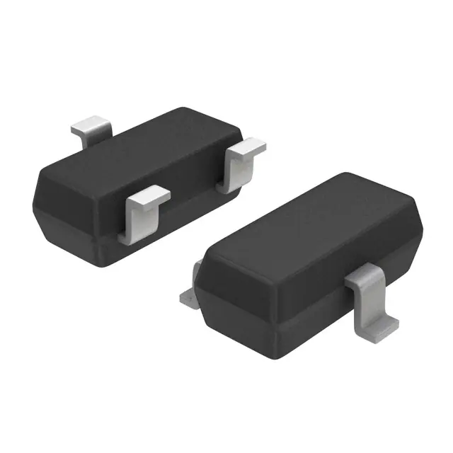
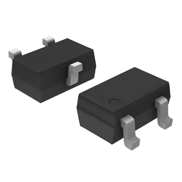
BAV70LT1G is an ON Semiconductor dual switching diode with common cathode configuration, 100V reverse voltage, 200mA forward current per diode and a compact SOT-23 package. A4 is the device marking code.
Your reliable partner for semiconductor solutions. Flychip supports customers from R&D to mass production with electronic component supply, BOM sourcing, PCB, SMT and PCBA services.
- 20+
- Years Component Supply
- BOM
- Multi-Part Sourcing
- PCBA
- PCB / SMT Support
- Part No.:
- BAV70LT1G
- Manufacturer:
- onsemi
- Category:
- Diode Arrays
- Package:
- TO-236-3, SC-59, SOT-23-3
- Datasheet:
- BAV70LT1G.pdf
- Description:
- BAV70LT1G is an ON Semiconductor dual switching diode with common cathode configuration, 100V reverse voltage, 200mA forward current per diode and a compact SOT-23 package. A4 is the device marking code.
- Quantity:


-
Quality Control
Supplier review, channel management and product verification before delivery.
-
Global Channels
International chip manufacturer and well-known distributor sourcing network.
-
BOM to Production
Component supply support from R&D prototype to mass production.
-
PCB / SMT / PCBA
Integrated manufacturing support to accelerate product development and delivery.
Product Details
BAV70LT1G (A4) ON Semiconductor Dual Switching Diode
BAV70LT1G is an ON Semiconductor dual switching diode featuring a common-cathode configuration and a compact SOT-23 surface-mount package. Each diode is rated for 100V reverse voltage and 200mA forward current. With a maximum reverse recovery time of 6ns under specified test conditions, this device is suitable for compact signal switching, steering and general-purpose low-current diode applications. A4 is the device identification marking shown in the manufacturer's marking diagram.
BAV70LT1G Technical Overview
BAV70LT1G is a monolithic dual switching diode from ON Semiconductor (onsemi). It integrates two independent diode junctions in a single SOT-23 package. Both anodes are brought out separately, while the cathodes are internally connected to a common terminal.
This arrangement is useful when a circuit needs two diode paths with a shared cathode node. It reduces component count and PCB placement area compared with using two individual discrete diodes.
The device is intended for switching and general signal-steering functions. It should not be treated as a power rectifier or a high-current protection component solely because its reverse-voltage rating is 100V.
| Parameter | Specification | Engineering Interpretation |
|---|---|---|
| Manufacturer | ON Semiconductor / onsemi | Original semiconductor manufacturer |
| Part Number | BAV70LT1G | Complete ordering number should be retained |
| Top Marking | A4 | Manufacturer device identification code |
| Device Type | Dual Switching Diode | Two diode junctions in one package |
| Configuration | Common Cathode | Two separate anodes share one cathode |
| Reverse Voltage | 100V | Maximum rated reverse voltage |
| Forward Current | 200mA | Maximum rating for each diode |
| Forward Voltage | Up to 1.25V | Maximum at 150mA test current |
| Reverse Recovery | 6ns Maximum | Specified switching test condition |
| Diode Capacitance | 1.5pF Maximum | At zero reverse voltage and 1MHz |
| Package | SOT-23 / TO-236 | 3-terminal surface-mount package |
| Package Case | CASE 318 / STYLE 9 | Manufacturer package identification |
| Junction Temperature | -55°C to +150°C | Maximum junction and storage temperature range |
| Compliance | Pb-Free / RoHS Compliant | Refer to applicable manufacturer documentation |
| Ordering Package | 3,000 pcs / Reel | BAV70LT1G standard tape-and-reel quantity |
Dual Diode Structure and SOT-23 Pin Assignment
BAV70LT1G uses a common-cathode topology. Pins 1 and 2 are the individual anode connections, and pin 3 is the shared cathode. This topology must be checked against the original PCB footprint and schematic before a replacement is approved.
| Pin | Connection | Electrical Function | PCB Design Consideration |
|---|---|---|---|
| Pin 1 | Anode 1 | First diode junction input | Connect according to the intended current path |
| Pin 2 | Anode 2 | Second diode junction input | Can be used as an independent signal path |
| Pin 3 | Common Cathode | Shared cathode terminal | Verify common-node polarity in the schematic |
Common-Cathode Functional Principle
Pin 1
Pin 3
Pin 2
Pin 3
Reverse Voltage, Forward Current and Diode Ratings
The electrical limits of BAV70LT1G are specified for each individual diode. When both junctions operate simultaneously, total package dissipation and board thermal conditions must also be considered.
| Electrical Parameter | Symbol | Rating | Test / Design Condition |
|---|---|---|---|
| Reverse Voltage | VR | 100V | Maximum rating |
| Forward Current | IF | 200mA | Each diode |
| Repetitive Peak Forward Current | IFRM | 1.5A | Specified pulse waveform, 1s period and 66% duty cycle |
| Breakdown Voltage | VBR | 100V minimum | Reverse breakdown test at 100µA |
| Reverse Leakage | IR | 1µA maximum | VR = 100V, TA = 25°C unless otherwise noted |
| Diode Capacitance | CD | 1.5pF maximum | VR = 0V, f = 1MHz |
| Junction Temperature | TJ | -55°C to +150°C | Maximum junction temperature range |
Forward Voltage Characteristics
| Forward Current | Maximum Forward Voltage | Engineering Meaning |
|---|---|---|
| 1mA | 0.715V | Low-current signal operation |
| 10mA | 0.855V | Common signal switching test point |
| 50mA | 1.000V | Moderate forward-current operation |
| 150mA | 1.250V | Higher-current forward test point |
Reverse Recovery, Capacitance and Signal Behavior
Switching performance is important when selecting a dual diode for signal steering, waveform control and fast logic-related circuits. BAV70LT1G has a specified maximum reverse recovery time of 6ns under the manufacturer's stated measurement conditions.
| Parameter | Specification | Test Conditions | Design Relevance |
|---|---|---|---|
| Reverse Recovery Time | 6ns maximum | IF = IR = 10mA; IR(REC) = 1mA; RL = 100Ω | Switching transition behavior |
| Junction Capacitance | 1.5pF maximum | VR = 0V; f = 1MHz | Signal loading and parasitic effects |
| Forward Voltage | 0.855V maximum at 10mA | TA = 25°C | Forward conduction loss |
| Reverse Leakage | 1µA maximum at 100V | TA = 25°C | Off-state leakage consideration |
The specified recovery characteristic supports applications where switching transition behavior matters.
The low specified capacitance helps limit capacitive loading in suitable signal paths.
Two diode junctions with a shared cathode can simplify compact steering networks.
Can be evaluated in suitable low-current clamping or steering circuits after checking transient energy and voltage limits.
Power Dissipation, Surge Current and Junction Temperature
BAV70LT1G uses a small SOT-23 package. Its usable current capability depends not only on the diode junction rating but also on PCB construction, copper area, ambient temperature and thermal resistance.
| Thermal Parameter | FR-5 Board | Alumina Substrate | Condition |
|---|---|---|---|
| Power Dissipation | 225mW | 300mW | TA = 25°C |
| Derating Above 25°C | 1.8mW/°C | 2.4mW/°C | Manufacturer test-board conditions |
| Thermal Resistance | 556°C/W | 417°C/W | Junction to ambient |
| Junction / Storage Temperature | -55°C to +150°C | Maximum specified range | |
Non-Repetitive Surge Current Reference
The manufacturer also provides non-repetitive forward surge current ratings at specified pulse durations. These are short-duration stress limits, not continuous operating current ratings.
| Pulse Duration | Non-Repetitive Surge Current | Application Note |
|---|---|---|
| 1µs | 31A | Very short transient condition |
| 10µs | 16A | Short pulse stress limit |
| 100µs | 10A | Transient evaluation |
| 1ms | 4.5A | Non-repetitive pulse only |
| 10ms | 2.5A | Non-repetitive pulse only |
| 100ms | 1.0A | Non-repetitive pulse only |
| 1s | 0.5A | Non-repetitive pulse only |
SOT-23 Footprint, Routing and Assembly Considerations
Correct footprint orientation and common-cathode routing are essential when integrating BAV70LT1G into a compact PCB. The three-terminal SOT-23 package offers a small board footprint, but incorrect pin mapping can reverse the intended diode paths.
| Design Area | Engineering Check | Recommended Action |
|---|---|---|
| Footprint | SOT-23 / CASE 318 | Use the manufacturer mechanical drawing |
| Pin Orientation | 1 = Anode, 2 = Anode, 3 = Cathode | Verify pin numbering against the PCB library |
| Cathode Routing | Shared cathode node | Check both signal paths in the schematic |
| Thermal Layout | Small package dissipation limit | Evaluate copper area and local heating |
| Signal Integrity | Low-capacitance signal path | Keep sensitive routing short where practical |
| Assembly | Surface-mount soldering | Follow the PCB assembler's qualified reflow process |
| Inspection | Polarity and solder quality | Inspect orientation, bridging and solder joints |
PCB Design Validation Checklist
Typical Applications for BAV70LT1G
The dual common-cathode structure makes BAV70LT1G useful in compact signal circuits where two diode junctions need to share a common electrical node. Application suitability depends on voltage, current, transient and switching requirements.
Supports low-current switching paths in electronic control and signal-processing circuits.
Two diode junctions can route signals toward a shared cathode node in suitable circuit configurations.
Can be evaluated in diode-based logic interfaces and signal isolation networks within its electrical limits.
Suitable for selected low-energy clamping or steering circuits after transient voltage and current verification.
May be used in appropriate signal paths where the package, recovery time and capacitance meet circuit requirements.
SOT-23 packaging supports high-density PCB layouts in suitable electronic products.
How to Select a Suitable Dual Switching Diode
A suitable alternative to BAV70LT1G must match more than its 100V voltage rating. Circuit topology, diode polarity, forward voltage, reverse recovery, junction capacitance, package pinout and power dissipation all influence the final selection.
| Selection Factor | BAV70LT1G Reference | What Engineers Should Verify |
|---|---|---|
| Diode Count | Dual diode | Two junctions required in one package |
| Topology | Common cathode | Shared terminal polarity must match |
| Reverse Voltage | 100V | Maximum circuit reverse voltage and margin |
| Forward Current | 200mA per diode | Average and peak current requirements |
| Forward Voltage | Up to 1.25V at 150mA | Conduction loss at actual operating current |
| Reverse Recovery | 6ns maximum under test conditions | Switching speed under application conditions |
| Capacitance | 1.5pF maximum at specified condition | Signal loading and frequency response |
| Package | SOT-23 | Footprint and pin orientation |
When BAV70LT1G Is a Good Fit
When two diode paths and a shared cathode are required in a small PCB area.
When forward current and package power remain within rated limits.
When the specified recovery performance is suitable for the actual circuit.
When a three-pin SOT-23 package meets manufacturing and layout requirements.
Replacement, Package Compatibility and Variant Review
BAV70LT1G replacement decisions should be based on electrical equivalence and mechanical compatibility. A device with a similar name or the same SOT-23 package is not automatically a valid drop-in replacement.
| Part / Variant | Key Difference | Engineering Consideration |
|---|---|---|
| BAV70LT1G | Standard BAV70L ordering variant | Target part for this product page |
| BAV70LT3G | Same device family; 10,000 pcs/reel | Verify procurement quantity and ordering code |
| SBAV70LT1G | S-prefix automotive-oriented variant | Separate ordering code; check qualification documents |
| Other BAV70 Devices | May differ by manufacturer or package | Compare pinout, ratings and switching data |
| Single Switching Diodes | One junction per component | May require two components and additional PCB area |
Replacement Approval Checklist
Authenticity, Traceability and Packaging Verification
For electronic component procurement, the complete manufacturer ordering code should be used in the BOM, quotation, purchase order and incoming inspection records. The surface marking A4 is useful for identification but should not replace the full orderable part number.
| Procurement Item | Expected Information | Verification Method |
|---|---|---|
| Manufacturer | ON Semiconductor / onsemi | Match manufacturer documentation |
| Ordering Number | BAV70LT1G | Check complete MPN on supplier records |
| Top Marking | A4 device code | Inspect package marking and date-code details |
| Package | SOT-23 / CASE 318 | Check package and terminal configuration |
| Standard Reel Quantity | 3,000 pcs / Tape & Reel | Verify order quantity and packing label |
| Alternative Reel Option | BAV70LT3G: 10,000 pcs / Reel | Do not confuse T1G and T3G |
| Environmental Information | Pb-Free / RoHS Compliant | Request applicable compliance documents |
| Lifecycle Status | Requires current confirmation | Check the manufacturer's current product listing |
| Lot Traceability | Lot and date-code information | Review original packaging and supplier records |
Confirm BAV70LT1G rather than relying only on the A4 top marking.
Review device code, date-code presentation, package condition and marking consistency.
Verify SOT-23 tape-and-reel packaging, label information and quantity.
Where required, perform forward-voltage, leakage, polarity and functional checks on incoming samples.
BAV70LT1G Frequently Asked Questions
What is BAV70LT1G?
What does A4 mean on BAV70LT1G?
What is the reverse-voltage rating?
What is the maximum forward current?
Is BAV70LT1G a common-cathode diode?
What package does BAV70LT1G use?
What is the reverse recovery time?
What is the difference between T1G and T3G?
Is BAV70LT1G AEC-Q101 qualified?
Can BAV70LT1G replace any dual diode?
Technical Evidence and Engineering Review Notice
This product review distinguishes manufacturer-published electrical specifications from practical engineering recommendations. The diode configuration, reverse voltage, forward current, forward voltage, recovery time, capacitance, thermal characteristics, package identification and ordering information are based on the ON Semiconductor BAV70L datasheet.
PCB recommendations, replacement assessment, incoming inspection and application examples represent engineering selection guidance. Final component suitability must be confirmed using the actual circuit conditions, PCB layout, environmental requirements and manufacturing process.
Manufacturer Technical References
- Primary Technical Reference: ON Semiconductor / onsemi BAV70L, SBAV70L Dual Switching Diode Datasheet, Rev.14, May 2023. Official Datasheet PDF
- Package Reference: SOT-23 (TO-236), CASE 318, STYLE 9. Refer to the manufacturer package drawing for PCB footprint and orientation.
- Ordering Reference: BAV70LT1G standard 3,000-piece tape-and-reel option; BAV70LT3G 10,000-piece tape-and-reel option.
From Component Sourcing to Production Delivery
Flychip has been providing electronic components to global customers for 20 years. We combine component supply, BOM services, PCB, SMT and PCBA support to help customers accelerate product development and delivery.
-
R&D Support
Fast sourcing support for prototype development, sample validation and early-stage engineering needs.
-
BOM Services
Multi-line BOM matching with component supply, alternative suggestions and procurement follow-up.
-
Mass Production
Stable supply coordination for production preparation, batch delivery and long-term purchasing needs.
-
Experienced Team
Over 15 years of channel management, quality control, sales management and organization management experience.
BAV70LT1G Technical Information
- Specifications
- FAQ
- Hot Sale
- Related Products
Specifications
- Product Attributes
- Attribute Value
- Manufacturer:
- onsemi
- Series:
- -
- Package/Case:
- TO-236-3, SC-59, SOT-23-3
- Packaging:
- Tape & Reel (TR)
- Product Status:
- Active
- Diode Configuration:
- 1 Pair Common Cathode
- Technology:
- Standard
- Voltage - DC Reverse (Vr) (Max):
- 100 V
- Current - Average Rectified (Io) (per Diode):
- 200mA (DC)
- Voltage - Forward (Vf) (Max) @ If:
- 1.25 V @ 150 mA
- Speed:
- Small Signal =< 200mA (Io), Any Speed
- Reverse Recovery Time (trr):
- 6 ns
- Current - Reverse Leakage @ Vr:
- 2.5 µA @ 70 V
- Operating Temperature - Junction:
- -55°C ~ 150°C
- Grade:
- -
- Qualification:
- -
- Mounting Type:
- Surface Mount
- Supplier Device Package:
- SOT-23-3 (TO-236)
FAQ
1. How to order BAV70LT1G on Flychip?
You can submit an RFQ directly on this page. Our sales team will review your quantity, delivery requirements and target price, then reply with a quotation as soon as possible.
2. How does Flychip verify the quality of BAV70LT1G?
We work with qualified channels including international chip manufacturers and well-known distributors. Our team pays close attention to supplier review, traceability, product condition and quality control.
3. Are the price and inventory of BAV70LT1G updated in real time?
Inventory and prices of electronic components may fluctuate frequently. The displayed data is for reference, and the final quotation will be confirmed by our sales team.
4. What payment methods are accepted?
Wire Transfer, PayPal, Alipay, WeChat, Credit Card, Western Union, MoneyGram and Escrow may be supported depending on the order and region.
5. How is shipping arranged?
We can arrange international shipping through DHL, UPS, FedEx, TNT and other logistics channels. Tracking information will be provided after shipment.
6. What is the return or replacement process for BAV70LT1G?
Please contact our sales team within the specified period if there are quantity differences, wrong items, or clear external defects. The product should remain unused and in its original packaging.
7. Can I request technical support for BAV70LT1G?
Yes. You can contact us for datasheet, package details, pin information and sourcing assistance related to BAV70LT1G.
Hot Sale
Related Products
-
-
BAV99-7-F
Diodes Incorporated
-
-
BAT54C-7-F
Diodes Incorporated
-
-
BAV99,215
Nexperia USA Inc.
-
-
BAT54SLT1G
onsemi
-
-
BAV70LT1G
onsemi
-
-
BAT54CLT1G
onsemi
-
-
BAT54S-7-F
Diodes Incorporated
-
-
BAV99LT1G
onsemi
-
-
BAT54S,215
Nexperia USA Inc.
-
-
BAS40-04LT1G
onsemi
-
-
MMBD1503-TP
Micro Commercial Co
-
-
BAV99WT1G
onsemi
BAV70LT1G Sourcing & Technical Support
BAV70LT1G is supplied by onsemi. This page provides key purchasing information including manufacturer, package, datasheet, stock reference, price reference and RFQ support.
As your reliable partner for semiconductor solutions, Flychip supports customers from research and development to mass production with electronic component supply, BOM sourcing, PCB, SMT and PCBA solutions.
Our sourcing partners include international chip manufacturers and well-known distributors. With rich experience in channel management, quality control and sales management, Flychip helps customers accelerate product development and delivery.
- Part Number
- BAV70LT1G
- Manufacturer
- onsemi
- Package
- TO-236-3, SC-59, SOT-23-3
- Category
- Diode Arrays
Quick RFQ Send your inquiry and our sales team will respond quickly.
Tips
Please check your information and try again.