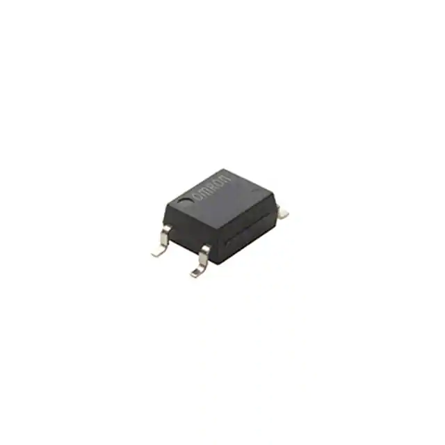
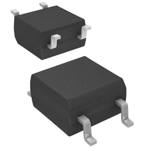
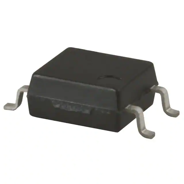
VO1400AEFTR VISHAY SOP-4 Solid-State Relay: Pinout, Specs, Applications & Replacement Guide
This complete guide explains the VO1400AEFTR from VISHAY, including SOP-4 pinout, 60 V load rating, 550 mA current capability, input-current design, isolation performance, applications, testing, equivalents, and replacement considerations.
VO1400AEFTR is a compact optically isolated solid-state relay from VISHAY for low- to moderate-current switching. This guide answers the questions engineers, buyers and repair technicians most often search for, including VO1400AEFTR datasheet specifications, SOP-4 pinout, 60 V load rating, 550 mA current capability, LED drive, isolation, thermal design, testing, equivalents and the newer VO1401AEFTR option.
VO1400AEFTR Search Guide: Find the Right Answer Faster
Searches for VO1400AEFTR usually come from several different technical intents. A designer may need the datasheet and input-drive requirements, a buyer may need the exact VISHAY SOP-4 part, and a repair technician may be looking for a VO1400AEFTR equivalent or replacement. Treating all of these searches as the same question makes an article less useful.
What Is the VO1400AEFTR?
The VO1400AEFTR from VISHAY is an optically isolated solid-state relay, commonly abbreviated as SSR. Its internal input is an LED. When a suitable forward current passes through this LED, light crosses an internal isolation barrier and activates the semiconductor output switch. The control circuit therefore does not need a direct electrical connection to the load circuit.
The device uses a 1 Form A configuration. Form A means normally open: with the input LED off, the output is in its high-resistance state. With adequate LED current, the output turns on and provides a conductive path between its two switch terminals.
This behavior gives the VO1400AEFTR several advantages over a small electromechanical relay. There is no moving armature, no coil, no mechanical contact bounce and no audible click. The package is also far smaller than many mechanical relays, which makes the device attractive for compact instrumentation, security equipment, industrial controls and high-density switching boards.
That does not mean an SSR is simply a perfect electronic version of a metal contact. The output has finite on resistance, the off state has a small leakage current, and the LED input requires careful current design. These differences are central to using the VISHAY VO1400AEFTR correctly.
VO1400AEFTR Key Specifications and Practical Meaning
A useful VO1400AEFTR datasheet review should connect each number to a real design decision. The table below does that instead of presenting specifications as an isolated list.
| Parameter | Specification | Why It Matters |
|---|---|---|
| Manufacturer | VISHAY | Use the exact VISHAY documentation when qualifying the part. |
| Relay Type | Optically isolated 1 Form A SSR | Normally-open electronic switching with galvanic isolation. |
| Package | 4-pin SOP, surface mount | Compact footprint and suitable for automated SMT assembly. |
| Load Voltage | 60 V DC or peak AC | Normal circuit voltage and transients must remain inside the rating with margin. |
| Load Current | 550 mA AC peak at stated conditions | Current capability must be derated with ambient temperature. |
| Peak Load Current | 1000 mA for 10 ms | A short-pulse limit, not a 1 A continuous-current rating. |
| LED Continuous Forward Current | 50 mA absolute maximum | Input current must be limited by a resistor or controlled driver. |
| LED Forward Voltage | 1.2 V typical at IF = 5 mA | Used when calculating the input current-limiting resistor. |
| Switch Turn-On Current | 2.5 mA typical, 5 mA max at 25°C test condition | Do not confuse the room-temperature test limit with a robust lifetime design target. |
| On Resistance | 0.6 Ω typical; datasheet electrical table specifies 2.5 Ω max at IF = 10 mA, IL = 500 mA, 25°C | RON creates voltage drop and I²R heating. |
| Off-State Leakage | 1 µA max at VL = 60 V, IF = 0 | Important for high-impedance and precision circuits. |
| Turn-On Time | 0.65 ms typical, 1.5 ms max at stated test condition | Suitable for control and instrumentation, not high-frequency power switching. |
| Turn-Off Time | 0.3 ms typical, 0.5 ms max at stated test condition | Useful when checking maximum practical switching rate. |
| Isolation Test Voltage | 3750 VRMS | Provides a strong input-to-output isolation barrier when the PCB layout also preserves isolation. |
| Total Power Dissipation | 800 mW at specified conditions | Thermal margin must be checked for sustained load current. |
| Ambient Temperature | -40°C to +85°C | Useful for industrial and instrumentation environments, subject to derating. |
VO1400AEFTR SOP-4 Pinout
The VO1400AEFTR pinout is simple, but pin orientation still matters. The input and output sides are isolated from each other, and the input LED is polarity sensitive.
| Pin | Name | Function | Design Note |
|---|---|---|---|
| 1 | Anode (A) | Positive terminal of input LED | Drive through a calculated current-limiting resistor or current source. |
| 2 | Cathode (K) | Negative terminal of input LED | Reversing LED polarity prevents normal turn-on and reverse voltage must remain within limits. |
| 3 | S2 | One terminal of the solid-state output | Part of the isolated load switch. |
| 4 | S1 | Other terminal of the solid-state output | Part of the isolated load switch. |
A four-pin SOP package is compact enough that board markings can be easy to misread during manual repair. Before laying out a PCB or replacing a failed component, confirm the pin-1 marker and the VISHAY mechanical drawing. Do not assume that another SOP-4 SSR uses the same internal orientation just because the body size looks similar.
How Does the VO1400AEFTR Work?
1. The Input LED Receives Controlled Current
A microcontroller, logic buffer or transistor driver sends current through the LED on pins 1 and 2. The LED converts the electrical control signal into light. Because the input behaves like an LED rather than a relay coil, the designer must control current rather than simply apply an unrestricted supply voltage.
2. Light Crosses the Isolation Barrier
The internal optical path transfers the control information without a metallic connection between the input and output. This is the core of the relay's galvanic isolation. The controller can therefore remain electrically separated from the switched circuit.
3. The Semiconductor Output Turns On
The optical receiver activates the output switching structure. The two output terminals move from a high-resistance off state to a lower-resistance on state. When LED current disappears, the device turns off again.
This operation is electronic, so there is no mechanical contact bounce. It is also silent and avoids the mechanical wear mechanisms that limit the life of conventional relays.
How Much Input Current Does VO1400AEFTR Really Need?
This is one of the most important VO1400AEFTR design questions. The electrical table lists a switch turn-on forward current of 2.5 mA typical and 5 mA maximum at 25°C under the specified test condition. It is tempting to choose a design current slightly above 5 mA and stop there.
VISHAY's 2026 application note explains why that approach can be too optimistic for a product that must operate across the full temperature range for years. The manufacturer starts with the 5 mA maximum turn-on current at 25°C, applies a factor of 2.1 for operation at 85°C, and then adds a 20% degradation allowance for aging.
The resulting recommendation is to design for at least 13.125 mA when guaranteed turn-on over the entire specified temperature range and expected lifetime is required.
This is a good example of the difference between a prototype and a robust production design. A board may work perfectly at room temperature with 5 mA today, but that does not automatically prove that the same margin will exist at high temperature after long operating life.
How to Calculate the VO1400AEFTR Input Resistor
The first-pass LED resistor equation is:
Assume a 5 V control signal, an LED forward voltage near 1.2 V and a design current of 13.125 mA. The idealized resistor value is:
This calculation is only the beginning. A production design should use worst-case values for the controller's output-high voltage, LED forward voltage, resistor tolerance and operating temperature. It should also verify that the controller pin can safely source the selected current.
For a 3.3 V MCU, the available voltage headroom is lower. If direct GPIO drive cannot guarantee enough LED current while staying inside the microcontroller's recommended output-current limits, use a small transistor, MOSFET or buffer as the input driver. That often gives better margin and avoids loading the MCU pin heavily.
Understanding the 60 V Load Voltage and 550 mA Current Ratings
The 60 V VO1400AEFTR load-voltage rating does not mean that 60 V should automatically be the normal working voltage. Real systems generate cable transients, inductive spikes, supply overshoot and switching noise. A reliable design keeps enough voltage margin between the expected worst-case circuit condition and the absolute device rating.
The same logic applies to the 550 mA load-current rating. The datasheet includes a load-current-versus-ambient-temperature curve because thermal conditions change the allowable operating point. A current that is comfortable at room temperature may leave much less margin in a sealed industrial enclosure at elevated temperature.
The 1 A figure in the absolute maximum table is a 10 ms peak load-current rating. It should not be described as a continuous 1 A capability. That distinction matters for motors, solenoids, capacitive charging currents and other loads with startup surges.
VO1400AEFTR RON, Voltage Drop and Power Loss
A mechanical relay contact can have very low closed-contact resistance. A semiconductor relay always has finite on resistance. For the VO1400AEFTR, the datasheet electrical table gives 0.6 Ω typical and 2.5 Ω maximum at the stated 25°C test condition of IF = 10 mA and IL = 500 mA.
Conduction power can be estimated with:
Because current is squared, heat rises quickly as load current increases. That is why RON, current and temperature must be evaluated together. A signal-routing application at a few milliamps places very different stress on the relay than a channel operating near several hundred milliamps for long periods.
RON also changes with temperature. The VISHAY datasheet provides a normalized on-resistance versus ambient-temperature curve, so designers working near the upper current range should not calculate loss from a room-temperature typical value alone.
What Does 3750 VRMS Isolation Mean?
The VO1400AEFTR isolation test voltage is 3750 VRMS. The datasheet also lists at least 5 mm clearance and at least 5 mm creepage between input and output terminals for the package.
This isolation can help separate microcontroller electronics from noisy field wiring, reduce unwanted ground-current paths and protect sensitive measurement circuits from load-side disturbances.
However, a component-level isolation rating does not automatically make the whole product compliant or safe. The PCB must preserve the required creepage and clearance. Connectors, copper pours, contamination, coating, enclosure construction, system voltage and applicable safety standards must all be considered.
VO1400AEFTR Switching Speed and Leakage Current
At the stated test condition of IF = 10 mA, VL = 20 V and IL = 100 mA, the datasheet specifies a 0.65 ms typical / 1.5 ms maximum turn-on time and a 0.3 ms typical / 0.5 ms maximum turn-off time.
Those numbers are fast compared with many mechanical relays but slow compared with a power MOSFET or dedicated high-speed semiconductor switch. VO1400AEFTR is therefore a better fit for control, instrumentation and signal routing than for high-frequency PWM power conversion.
The off state also has finite leakage. VISHAY specifies up to 1 µA at 60 V with the input off. For normal digital loads this may be insignificant. In high-impedance measurement circuits, however, one microamp can become part of the error budget.
Where Is VO1400AEFTR Commonly Used?
Security Systems
VISHAY lists security systems as a target application. The relay can isolate alarm inputs, access-control interfaces and external low-voltage wiring from the main logic board while providing silent electronic switching.
Instrumentation and Measurement Equipment
Instrumentation benefits from compact isolated switching, especially when a controller must connect or disconnect signal paths without a mechanical relay. Leakage, RON and switching time should be included in the measurement error analysis.
Industrial Controls
Industrial equipment often needs a clean boundary between logic electronics and field-side circuits. The VO1400AEFTR can provide that isolation for suitable 12 V, 24 V and other low-voltage control channels when the load stays within voltage, current and thermal limits.
PLC and Digital I/O Interfaces
For suitable load levels, the relay can act as an isolated switch between logic circuitry and external control signals. The absence of contact bounce simplifies digital interpretation, while the optical barrier helps separate ground domains.
Automated Test Equipment
A small SOP-4 package and no moving contacts can be useful in test systems that require many switching channels. Long cycle life and silent operation are attractive, but designers must verify that RON and leakage are acceptable for the measured signals.
Battery and Low-Voltage Systems
A 60 V load rating gives useful headroom for many battery-powered and low-voltage industrial systems. The relay can be used for isolated enable lines, signal routing and low-current power paths where its on resistance and current rating are appropriate.
VO1400AEFTR vs Mechanical Relay
| Comparison | VO1400AEFTR | Mechanical Relay | Design Impact |
|---|---|---|---|
| Switching Element | Semiconductor output | Moving metal contacts | SSR has no mechanical wear mechanism. |
| Noise | Silent | Often audible click | Useful in quiet instruments and compact equipment. |
| Contact Bounce | No mechanical bounce | Bounce can occur | SSR gives clean electronic transitions. |
| On-State Loss | Finite RON and voltage drop | Often very low contact resistance | SSR thermal loss must be calculated. |
| Off-State Behavior | Small leakage current | Very high open-contact resistance | Leakage matters in high-impedance circuits. |
| Size | Compact SOP-4 | Usually larger | SSR supports dense PCB layouts. |
| Input | LED current | Coil current | Different driver design is required. |
VO1400AEFTR vs Standard Optocoupler
VO1400AEFTR uses optical isolation, but it is not just a conventional signal optocoupler. A standard phototransistor optocoupler usually transfers a logic or analog signal to another electronic stage. The VO1400AEFTR integrates optical control with an output designed to behave as an isolated normally-open switch.
That distinction affects selection. If the goal is digital signal transfer, a standard optocoupler may be enough. If the goal is to open and close a low-current isolated load path without adding a separate output transistor stage, an SSR such as VO1400AEFTR can simplify the design.
VO1400AEFTR vs VO1401AEFTR: What Changed?
A particularly useful search comparison is VO1400AEFTR vs VO1401AEFTR. VISHAY's industrial SSR portfolio identifies VO1401AEFTR as the next generation of the existing VO1400AEFTR. This makes it more relevant than comparing the VO1400AEFTR with a random SSR that happens to share a 60 V rating.
| Comparison | VO1400AEFTR | VO1401AEFTR | Why It Matters |
|---|---|---|---|
| Manufacturer | VISHAY | VISHAY | Same manufacturer family simplifies documentation review. |
| Contact Form | 1 Form A | 1 Form A | Both provide normally-open SSR operation. |
| Package | SOP-4 | SOP-4 | Mechanical compatibility still requires footprint verification. |
| Load Voltage | 60 V | 60 V | Same headline voltage class. |
| Continuous Load Current | 550 mA class | 550 mA | Current requirement remains similar, but check exact conditions. |
| On Resistance | Legacy device; VISHAY front-page feature lists max RON 5 Ω | 0.6 Ω portfolio value; datasheet 0.6 Ω typ / 2.5 Ω max at stated test condition | The newer device targets improved conduction performance. |
| Product Position | Existing / legacy design option | VISHAY identifies it as next generation of VO1400AEFTR | New projects should evaluate the newer device before freezing the BOM. |
Do not treat "next generation" as an automatic drop-in approval. Before substitution, compare the latest datasheets, land pattern, pin numbering, LED current, RON, leakage, switching times, insulation data, agency approvals and production qualification requirements.
How to Choose a VO1400AEFTR Equivalent or Replacement
There is no universal VO1400AEFTR equivalent that is correct for every circuit. An SSR replacement must match the function that the original part performs in the real system.
Check at least the following:
- 1 Form A normally-open output configuration
- Maximum DC or peak AC load voltage
- Continuous and peak load current
- On resistance at the relevant input and load conditions
- Off-state leakage current
- Input LED forward voltage and required forward current
- Turn-on and turn-off times
- Isolation test voltage
- Creepage and clearance requirements
- SOP-4 package dimensions and PCB land pattern
- Pin assignment and orientation
- Ambient-temperature range and thermal derating
- Agency approvals required by the end product
- Tape-and-reel and manufacturing compatibility
For repair work, mechanical fit can be just as important as electrical ratings. For a new design, lifecycle and active manufacturer support deserve more weight. That is why VO1401AEFTR is worth evaluating when a new VISHAY SOP-4 SSR is being selected.
How to Test a VO1400AEFTR Solid-State Relay
Step 1: Confirm the SOP-4 Pinout
Identify pin 1, then confirm the input anode/cathode and the two output terminals. Do not begin by applying voltage to unknown pins.
Step 2: Check the Input LED
A multimeter diode-test function can provide a basic check of the LED junction. For a powered test, always use a current-limited source or a correctly sized series resistor.
Step 3: Measure the Output With the Input Off
The output should remain in its off state. A near-zero resistance reading in both directions with no LED current can indicate damage, although in-circuit measurements can be affected by parallel components.
Step 4: Apply Controlled LED Current
Drive the input with a known current. For a simple room-temperature functional test, use a safe current based on the datasheet. For a production validation, use the current defined by your worst-case design analysis.
Step 5: Confirm Output Conduction
Use a known load and power supply to check that the output switches on and that the measured voltage drop is reasonable for the load current. Avoid judging RON from a cheap resistance measurement alone if accurate qualification is required.
Step 6: Remove the LED Drive
Confirm that the output returns to its off state and that leakage is consistent with the needs of the circuit.
A bench test can identify a gross failure, but it does not certify 3750 VRMS isolation, worst-case RON, lifetime, high-temperature performance or all datasheet limits.
Common VO1400AEFTR Design Mistakes
Using the 25°C Turn-On Current as the Whole Design
This ignores temperature and LED aging. For guaranteed lifetime operation, VISHAY's application note recommends a much larger design margin, leading to the 13.125 mA minimum target described earlier.
Calling the 1 A Peak Rating a 1 A Relay
The 1 A rating is specified for a 10 ms peak. The normal load-current rating is 550 mA under stated conditions and must still be thermally derated.
Ignoring RON
At hundreds of milliamps, even a few ohms can produce meaningful voltage drop and heat. Always calculate I²R loss.
Assuming Zero Leakage When Off
The datasheet specifies up to 1 µA at 60 V. That may be irrelevant for a digital load but important for a high-impedance analog input.
Driving the Input LED Without Current Limiting
The input is an LED, not a voltage-input logic gate. A resistor, current source or controlled driver is required.
Ignoring Isolation Layout
Placing copper, vias or other conductive features across the intended barrier can undermine the isolation advantage of the SSR.
Selecting an Equivalent From Package Appearance
Two SOP-4 relays can have different pin assignments, current requirements, RON, leakage, voltage ratings or approvals.
Thermal Design and Derating
Thermal design is particularly important when VO1400AEFTR operates near the upper end of its load-current range. The key relationship is straightforward: output current creates conduction loss, conduction loss creates heat, and higher ambient temperature reduces the available thermal margin.
The datasheet specifies an ambient range of -40°C to +85°C and includes both load-current and output-power derating curves. Those curves should be part of the design review, especially for sealed enclosures, industrial cabinets, densely populated boards and applications where several SSR channels operate simultaneously.
A prototype running on an open bench at 23°C may not reveal the same junction-temperature stress as the final product operating inside a warm enclosure. Validate the worst credible ambient condition, not only room temperature.
Can VO1400AEFTR Be Driven by 3.3 V or 5 V Logic?
The datasheet describes the input as TTL/CMOS compatible, but that phrase should not replace current calculation. The microcontroller sees an LED load, so the available GPIO voltage and current capability must support the desired LED current.
For 5 V logic, there is usually more voltage headroom for the resistor. For 3.3 V logic, verify the minimum GPIO high voltage and maximum LED forward voltage at the required current. If direct drive would force the GPIO close to its recommended current limit, use an external transistor or buffer.
The most robust design asks two questions separately: "Can the relay turn on?" and "Can the controller drive it safely under every specified condition?" Both answers need to be yes.
VO1400AEFTR Procurement and Supplier Checks
When buying VISHAY VO1400AEFTR SOP-4 components for production or repair, verify more than unit price. The exact manufacturer part number, package, tape-and-reel format, date code, lot traceability and documentation can all matter.
For safety-isolated or industrial products, a substitute with unknown origin can create risk in areas that are difficult to detect with a simple incoming resistance test, including insulation quality, LED efficiency, leakage and long-term reliability.
For new designs, also compare the VO1401AEFTR because VISHAY identifies it as the next-generation device in this 60 V / 550 mA SOP-4 class.
Frequently Asked Questions About VO1400AEFTR
What type of component is VO1400AEFTR?
It is a VISHAY optically isolated 1 Form A normally-open solid-state relay in a four-pin SOP surface-mount package.
What is the VO1400AEFTR load voltage?
The absolute maximum table specifies 60 V DC or peak AC load voltage. Real designs should retain margin for transients and supply variation.
What is the VO1400AEFTR load current?
The datasheet lists 550 mA AC peak load current at the stated conditions, with a 1 A peak limit for 10 ms. Use the thermal derating curve for real operating temperatures.
What is the VO1400AEFTR pinout?
Pin 1 is the LED anode, pin 2 is the cathode, pin 3 is S2 and pin 4 is S1.
What is the isolation rating?
The VO1400AEFTR isolation test voltage is 3750 VRMS. The package datasheet also lists at least 5 mm clearance and 5 mm creepage between input and output terminals.
How much input current does VO1400AEFTR need?
The 25°C turn-on-current table lists 5 mA maximum under the specified test condition. VISHAY's May 2026 application note recommends designing for at least 13.125 mA when full temperature range and long-term degradation are included.
Can VO1400AEFTR work with Arduino or a microcontroller?
Yes, if the LED current is properly limited and the GPIO or external driver can provide the required current. For high reliability, check worst-case output voltage, LED VF, temperature and current capability.
Does VO1400AEFTR have contact bounce?
No mechanical contact is used, so there is no mechanical contact bounce.
What is the difference between VO1400AEFTR and VO1401AEFTR?
Both are VISHAY 1 Form A SOP-4 SSRs in the 60 V / 550 mA class. VISHAY identifies VO1401AEFTR as the next generation of VO1400AEFTR and positions it with improved low-RON performance.
What should I check when choosing a VO1400AEFTR replacement?
Compare contact form, load voltage, current, RON, leakage, LED drive, switching speed, isolation, thermal limits, SOP-4 footprint, pinout and required agency approvals.
VO1400AEFTR Design Checklist
- Confirm the exact VISHAY VO1400AEFTR orderable part and SOP-4 footprint.
- Keep normal and transient load voltage safely inside the 60 V rating.
- Check load-current derating at the worst ambient temperature.
- Do not treat the 1 A / 10 ms peak current as a continuous rating.
- Calculate output I²R power loss using a conservative RON value.
- Verify that off-state leakage is acceptable for the load.
- Calculate the LED resistor from worst-case control voltage and LED VF.
- Use adequate LED current margin for temperature and aging.
- Confirm the MCU or driver can source the required LED current safely.
- Check turn-on and turn-off time against the required switching rate.
- Preserve PCB creepage and clearance across the isolation barrier.
- Validate the final circuit at temperature, not only on a room-temperature bench.
- For a new design, compare VO1401AEFTR before freezing the BOM.
Final Engineering View: Where VO1400AEFTR Fits Best
The VISHAY VO1400AEFTR SOP-4 is best understood as a compact isolated electronic switch rather than as a universal replacement for every mechanical relay. Its 60 V load rating, 550 mA current class, 3750 VRMS isolation and four-pin SMT package make it useful in security systems, instrumentation, industrial controls, test equipment and isolated low-voltage interfaces.
Its strongest design advantages are silent operation, no mechanical contact bounce, no moving contact wear and a small footprint. Its main design tradeoffs are equally important: finite RON, microamp-level off-state leakage, LED input-current requirements and thermal derating at elevated temperature.
For GEO and technical search intent, one point deserves special emphasis: the input-current value required for a reliable product is not necessarily the same as the room-temperature current that makes one sample turn on. VISHAY's 2026 application note explicitly builds temperature and aging margin into the calculation and arrives at 13.125 mA. That is the kind of detail that separates a datasheet summary from a useful engineering guide.
For replacement work, match the complete electrical and mechanical behavior rather than only "60 V, 550 mA, SOP-4." For new designs, evaluate the VO1401AEFTR, which VISHAY describes as the next generation of the existing VO1400AEFTR. A newer part may provide better conduction performance while retaining the same general SSR concept.
The practical selection rule is simple: use VO1400AEFTR when its isolation, switching speed, load current, leakage, RON, package and input-current requirements fit the actual circuit with comfortable margin. When those conditions are understood, this small SOP-4 solid-state relay can provide a clean and reliable interface between logic electronics and isolated load circuitry.
.jpg)