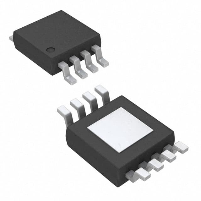
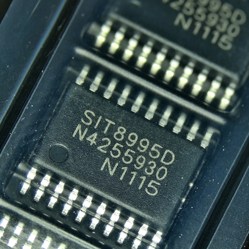
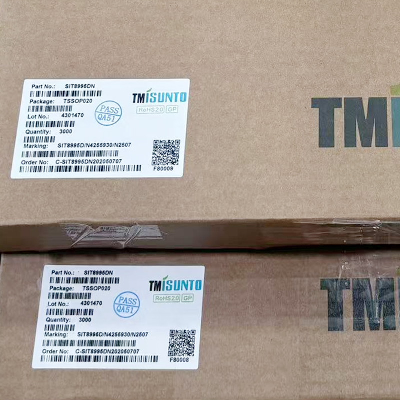
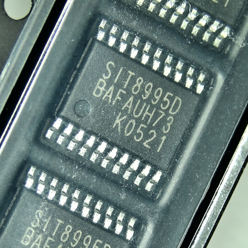
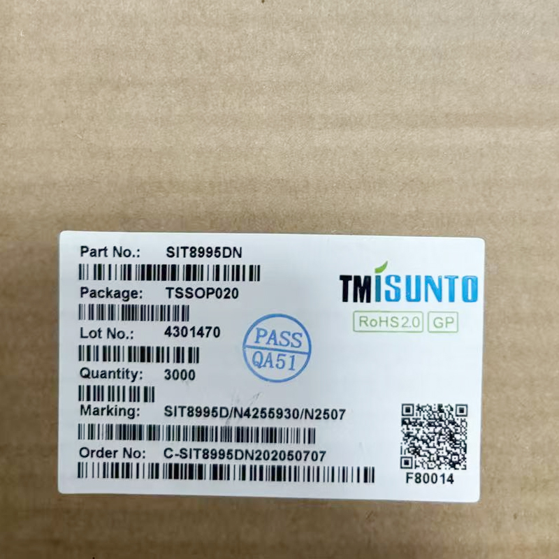
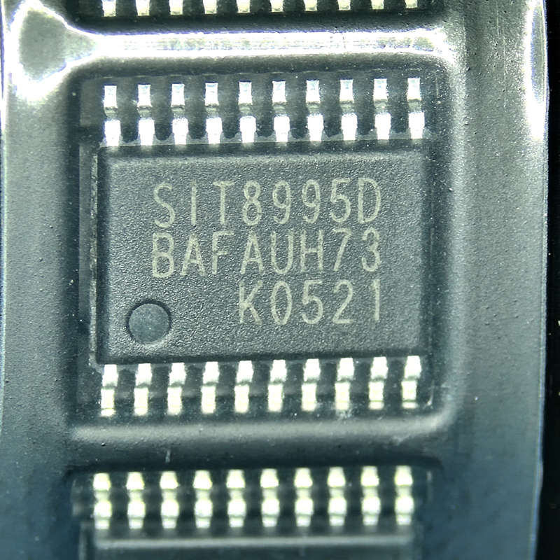


For engineers, battery-pack manufacturers, repair companies, PCB designers, and electronic component buyers, the important point is that the SIT8995D battery protection IC is not simply a voltage detector. It acts as a hardware safety supervisor between the battery cells, external MOSFETs, current-sense network, charger, and load. This makes it suitable for many 4S and 5S battery management systems where reliable protection must continue even if the main microcontroller is not running.
What Is SIT8995D?
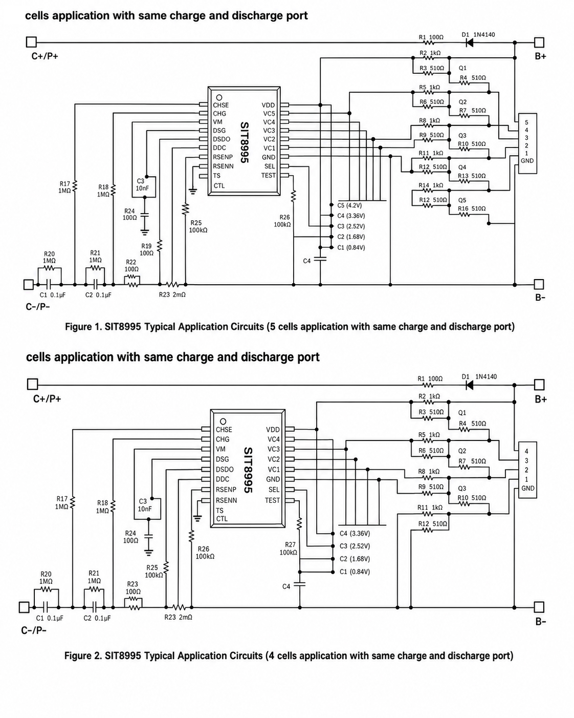
The SIT8995D belongs to the SIT8995 family of multi-cell Li-Ion and Li-Polymer battery protector ICs. The family is designed for four-cell or five-cell battery configurations and uses a SEL function to configure the required cell count.
The device integrates high-accuracy cell-voltage detection, current detection, delay control, temperature monitoring, charge and discharge protection logic, MOSFET control, battery balancing logic, adapter detection, and sleep-mode management.
In practical terms, the chip continuously asks several important safety questions:
- Is any battery cell charged above the allowed voltage?
- Is any cell discharged below the allowed voltage?
- Is discharge current too high?
- Is charge current too high?
- Has a short circuit occurred?
- Is the battery too hot during charging?
- Is the battery too cold during charging?
- Is the battery too hot during discharge?
- Should charging or discharging MOSFETs be turned off?
- Should the system enter a low-power state?
- Should cell-balancing control become active?
This combination makes SIT8995D more useful than a simple voltage protection IC in multi-cell battery systems.
SIT8995D Key Specifications
| Parameter | SIT8995D |
|---|---|
| Product Type | Multi-cell battery protection IC |
| Battery Type | Li-Ion / Li-Polymer |
| Supported Cell Count | 4 cells or 5 cells |
| Overcharge Detection Voltage | 3.75 V per cell |
| Overcharge Recovery Voltage | 3.55 V per cell |
| Balance Turn-On Voltage | 3.515 V |
| Over-Discharge Detection Voltage | 2.2 V per cell |
| Over-Discharge Recovery Voltage | 2.7 V per cell |
| Discharge Overcurrent Detection Voltage | 0.1 V |
| Charge Overcurrent Detection Voltage | 0.04 V |
| Operating Voltage Range | 3 V to 40 V |
| Normal Operating Current | 20 µA maximum |
| Sleep Mode Current | 3 µA maximum |
| Operating Temperature | -40°C to +85°C |
| Package | TSSOP20 |
These values are especially important when selecting the correct SIT8995 family member. SIT8995A, SIT8995B, SIT8995C, SIT8995D, SIT8995F, and SIT8995G are related devices, but their protection thresholds are not identical. The final part number should therefore be selected according to the battery cell specification rather than only by package or family name.
Why the SIT8995D Protection Thresholds Matter
One of the most important decisions in a battery protection design is choosing the correct voltage thresholds. A protection IC can contain many useful functions, but those functions provide little value if the thresholds do not match the cells being protected.
For SIT8995D, the listed overcharge protection threshold is 3.75 V per cell. The overcharge recovery value is 3.55 V. Its over-discharge detection threshold is 2.2 V, while the recovery level is 2.7 V.
These values should always be compared with the battery manufacturer's recommended charge and discharge limits.
This leads to an important design principle: do not choose SIT8995D only because it supports four or five cells. First confirm that its voltage thresholds match the intended cell chemistry and pack design.
Two battery packs may both be described as "4S lithium batteries," yet require different protection settings. Cell count alone is therefore not enough information for IC selection.
How SIT8995D Protects a 4S or 5S Battery Pack
In a typical battery management circuit, SIT8995D is connected to each cell through a voltage-sensing network. It also monitors current through an external current-sense path and receives temperature information from an external NTC thermistor.
The IC controls charging and discharging through external switching devices. Under normal conditions, the battery pack can charge and discharge normally. When a fault is detected for longer than the defined protection delay, the IC changes its control outputs so that the external power path can be interrupted.
This separation between detection and power switching is useful. The SIT8995D performs sensitive monitoring and logic, while external MOSFETs handle the higher battery current.
SIT8995D Overcharge Protection
Overcharging a lithium battery cell can damage the cell and reduce system safety. The SIT8995D therefore monitors the voltage of each connected cell rather than only measuring the total battery-pack voltage.
For the SIT8995D version, the overcharge detection level is 3.75 V per cell. If any monitored cell remains above the required threshold for the specified delay time, the device enters an overcharge protection state.
This individual-cell approach is important because cells in a series battery pack are never perfectly identical.
Consider a five-cell pack. The total pack voltage may appear reasonable, yet one cell could already be too high while another cell is lower than expected. Monitoring only total pack voltage could miss this condition.
By watching each cell separately, SIT8995D can react to the actual weak point in the pack.
The 3.55 V overcharge recovery threshold provides hysteresis between entering and leaving the protection state. Hysteresis helps prevent the system from rapidly switching between protection and normal operation when the cell voltage is close to the threshold.
SIT8995D Over-Discharge Protection
Deep discharge is another important risk for rechargeable lithium battery packs. If a cell voltage falls too low, cell life and future performance may be affected.
The SIT8995D monitors each battery cell for an under-voltage condition. For the D version, the listed over-discharge threshold is 2.2 V per cell.
When the condition remains valid for the required delay, the IC disables the normal discharge path through its discharge control logic.
The listed recovery threshold is 2.7 V. This means the device does not simply reconnect the load immediately when voltage moves slightly above the trip point.
The difference between 2.2 V detection and 2.7 V recovery creates a stable protection window.
This is another example of why a battery protection IC should be viewed as a state-control device rather than as a simple comparator.
Two-Stage Discharge Overcurrent Protection
The SIT8995 architecture includes two levels of discharge overcurrent detection. This allows the system to distinguish between a moderate but abnormal overload and a more serious high-current event.
The first overcurrent stage uses a lower detection level and can use a longer delay. The second stage uses a higher detection level and can react more quickly.
This approach is useful because battery loads are not always smooth.
Motors, compressors, power tools, converters, and other electronic loads may briefly draw high current during startup. A protection circuit that responds too quickly to every current spike may cause unwanted shutdowns.
On the other hand, a serious overload must not be allowed to continue for too long.
Using multiple protection levels gives the designer more control over this trade-off between false triggering and fast fault response.
SIT8995D Short-Circuit Protection
A short circuit is different from an ordinary overload. Current can increase extremely quickly, so the battery protection system needs a dedicated response.
The SIT8995 family includes short-circuit detection based on the voltage across the current-sensing path. When the detected voltage exceeds the short-circuit threshold for the required delay, the discharge path is turned off.
After the short circuit or abnormal load is removed, the IC can detect the changed condition and allow the protection state to recover according to its control logic.
This function is especially important in battery packs used in portable electronics, industrial devices, power tools, backup systems, and products where the external terminals may accidentally be shorted.
SIT8995D Charge Overcurrent Protection
Battery safety is not only about discharge current. An abnormal charger, damaged cable, wrong power source, or circuit fault can also cause excessive charging current.
The SIT8995D includes charge overcurrent detection through the differential current-sense path.
For the SIT8995D variant, the listed charge overcurrent detection voltage is 0.04 V.
It is important to understand that this value is a sense voltage, not directly the charging current in amperes.
The actual protection current depends on the external current-sense resistance and the complete circuit design.
A common design mistake is to read "0.04 V charge overcurrent detection" and treat it as a current rating. That is incorrect. The designer must use Ohm's law with the selected sense resistance and then include resistor tolerance, PCB resistance, current range, and thermal behavior.
Why Current-Sense Design Is Critical
The current-sense resistor or current-sense path is one of the most important external parts around a battery protection IC.
The basic relationship is:
Protection Current ≈ Current Detection Voltage ÷ Sense Resistance
This means that the same SIT8995D can protect different current levels when used with different sensing resistance values, provided that all datasheet limits are respected.
However, simply choosing a very small resistor is not enough.
The designer also needs to consider resistor power loss, heat generation, pulse capability, tolerance, Kelvin sensing, PCB copper resistance, and the maximum fault current expected from the battery.
For accurate current detection, the sensing traces should be routed carefully so that high-current PCB copper does not introduce unwanted measurement error.
SIT8995D Temperature Protection
Temperature monitoring adds another important safety layer to the SIT8995D battery protection system.
The SIT8995 family supports an external NTC thermistor, with a 103AT thermistor with β = 3435 recommended in the reference documentation.
The protection system includes three main thermal conditions:
- Charging high-temperature protection
- Charging low-temperature protection
- Discharging high-temperature protection
Typical family thresholds include approximately 50°C for charging high-temperature protection, -5°C for charging low-temperature protection, and 70°C for discharging high-temperature protection.
This distinction between charging and discharging temperatures is important because lithium cells can have different safe operating limits during charge and discharge.
A battery pack should therefore not use only a single "too hot" temperature limit for every operating state.
SIT8995D Cell Balancing Control
Cell imbalance is a common challenge in series-connected battery packs. Even cells from the same production batch can slowly develop different voltage levels because of capacity variation, self-discharge, temperature, age, and operating history.
The SIT8995 family provides cell balance control, and the SIT8995D has a listed balance turn-on voltage of 3.515 V.
The device uses a parity-style balance method in which adjacent cells are not balanced at exactly the same time.
From a system-design point of view, this is useful because balancing is not only an electrical issue. It also creates heat. Preventing adjacent balance channels from operating simultaneously can help distribute thermal stress across the PCB and battery pack.
However, designers should not confuse balance control with a high-power active balancing system. The exact balancing current and thermal behavior depend on the external circuit connected to the balance-control outputs.
4-Cell and 5-Cell Configuration
One practical advantage of SIT8995D is its ability to support both four-cell and five-cell battery packs.
A SEL configuration is used to define the application.
This can simplify purchasing for manufacturers that produce related 4S and 5S products, because the same protection family can be used across multiple battery-pack designs.
However, flexible configuration also creates a manufacturing responsibility.
The selected cell configuration should be clearly controlled in the schematic, PCB documentation, BOM, assembly instructions, and functional test process. An incorrect configuration in production can create a serious battery-protection problem.
Low-Power Sleep Mode
Battery protection electronics consume energy even when the main product is turned off. For battery-powered equipment stored for weeks or months, every microamp matters.
The SIT8995 family is designed for low power consumption. The datasheet lists normal operating current up to 20 µA and sleep-mode current up to 3 µA.
The device can enter sleep mode after remaining in an over-discharge condition for a defined period when no charger is connected.
In sleep mode, most internal blocks are shut down, reducing energy use from an already deeply discharged battery.
This is more important than it may first appear.
A protection IC that continues consuming unnecessary current after the cells have reached an under-voltage state could slowly discharge them even further during long storage.
Charging From a Deeply Discharged Battery
The SIT8995 architecture also includes support for charging from a very low battery condition, often described as charging from 0 V.
This feature helps the protection system recover a deeply discharged pack when a suitable charger is connected, provided that the battery itself remains safe to recharge.
The distinction is important: a protection IC being able to enable a recovery path does not automatically mean that every deeply discharged lithium cell should be recharged.
Battery manufacturer limits, cell condition, storage history, temperature, swelling, physical damage, and the complete charger design must still be considered.
SIT8995D Is a Protection IC, Not a Battery Charger
One of the most useful distinctions for buyers and new engineers is understanding what SIT8995D does not do.
SIT8995D is a battery protection IC. It is not a complete battery charger.
A charger controls how energy enters the battery, including charging voltage and current profiles. The SIT8995D instead monitors whether the battery is operating inside safe limits and can interrupt charging when an unsafe condition is detected.
A complete battery product may therefore contain both a charger IC and an SIT8995D protection IC.
These two devices have different jobs and can form two independent layers of battery control.
SIT8995D Is Not a Fuel Gauge Either
SIT8995D should also not be confused with a fuel-gauge IC.
A battery fuel gauge estimates information such as state of charge, remaining capacity, time to empty, or battery health.
The SIT8995D focuses on protection conditions such as voltage, current, temperature, and short circuits.
A more advanced battery management system may therefore use:
- SIT8995D for hardware battery protection
- A charger IC for controlled charging
- A fuel-gauge IC for capacity estimation
- A microcontroller for communication and system management
Understanding these roles helps prevent incorrect component selection.
SIT8995D in a BMS Architecture
In a practical Battery Management System, the SIT8995D can be viewed as the hardware safety layer.
A typical system may include:
- Four or five rechargeable lithium cells
- SIT8995D battery protection IC
- External charge and discharge MOSFETs
- Current-sense resistor
- NTC temperature sensor
- Cell-balancing resistors and switching components
- Input protection components
- Charger connection
- Load connection
- Optional microcontroller
- Optional battery fuel gauge
One of the strongest reasons to use a dedicated protection IC is independence from software.
If a microcontroller crashes, firmware becomes corrupted, or communication fails, hardware protection can still monitor critical battery conditions.
This does not eliminate the need for good firmware. It simply creates another safety layer.
Why Protection Delay Time Matters
Protection thresholds usually receive most of the attention, but delay time is just as important.
Real battery systems contain switching noise, load transients, motor startup current, cable inductance, charger transitions, and electromagnetic interference.
If every short voltage spike triggered protection immediately, the battery pack might shut down during normal use.
The SIT8995 family therefore uses delay logic for different protection conditions. Some delays are internally defined, while selected discharge and current-related delays can be influenced by external timing components.
A useful way to think about delay time is as a noise filter in the time domain.
The voltage threshold asks, "How large is the fault?" The delay asks, "How long has the fault existed?"
A safe and stable protection design needs both answers.
PCB Layout Tips for SIT8995D
Good PCB layout is essential because SIT8995D measures relatively small voltage differences while being located close to high-current battery paths.
Keep Cell-Sense Traces Clean
Cell-voltage sensing lines should be kept away from switching nodes, MOSFET gates, inductors, and high-current copper where possible.
Use Careful Current-Sense Routing
Current-sense inputs should connect directly to the intended sensing points. Kelvin-style routing can reduce measurement errors caused by PCB copper resistance.
Keep High Current Away From Sensitive Ground
Charge and discharge current should not share unnecessary PCB paths with sensitive analog references.
Place Filtering Components Close to the IC
Components used to filter cell-sense signals should be placed close to the SIT8995D so that long traces do not pick up additional noise after the filter.
Consider MOSFET Gate Routing
Charge and discharge MOSFET gate traces should be short and controlled. Excessive gate-loop area can increase switching noise and unwanted coupling.
Plan Thermal Paths
The SIT8995D itself is a low-power control IC, but MOSFETs, current-sense resistors, and balancing resistors can generate significant heat. PCB placement should therefore be planned as one thermal system.
Common Applications for SIT8995D
The SIT8995D can be considered for many 4S and 5S rechargeable battery products when its voltage thresholds match the selected cells.
Potential application areas include:
- Portable electronic equipment
- Rechargeable industrial instruments
- Smart household devices
- Backup battery modules
- Portable communication equipment
- Battery-powered measurement tools
- Consumer electronics
- Battery packs for embedded systems
- Small energy-storage modules
- Custom 4S and 5S BMS boards
The key condition remains the same: application type alone does not determine compatibility. Cell voltage limits, current, MOSFET rating, thermal conditions, charger design, and protection requirements must all be verified.
SIT8995D vs a Microcontroller-Based Protection System
It is technically possible to measure cell voltage and current with a microcontroller, ADC, and external analog circuits. However, relying only on firmware for primary battery protection creates additional failure paths.
A dedicated IC such as SIT8995D offers predefined hardware protection behavior with independent detection circuits.
A microcontroller is still useful for:
- Displaying battery level
- Recording fault history
- Communicating with a host system
- Controlling operating modes
- Estimating battery capacity
- Logging temperature
The most robust architecture often uses hardware protection and software management together rather than asking one device to perform every job.
How to Select SIT8995D Correctly
Before adding SIT8995D to a new design, check the following points.
- Confirm whether the battery pack uses four or five cells in series.
- Check the cell manufacturer's maximum charge voltage.
- Check the minimum allowed discharge voltage.
- Compare those limits with SIT8995D protection thresholds.
- Calculate discharge overcurrent protection using the selected sense resistance.
- Calculate charge overcurrent protection.
- Check maximum normal current and peak current.
- Select suitable external MOSFETs.
- Check MOSFET voltage rating and safe operating area.
- Verify temperature protection requirements.
- Check NTC thermistor characteristics.
- Review sleep and recovery behavior.
- Calculate balance resistor power dissipation.
- Review PCB creepage, spacing, and high-current routing.
- Test every protection mode on real hardware.
This checklist is more useful than selecting the part only from a distributor description.
SIT8995D TSSOP20 Package
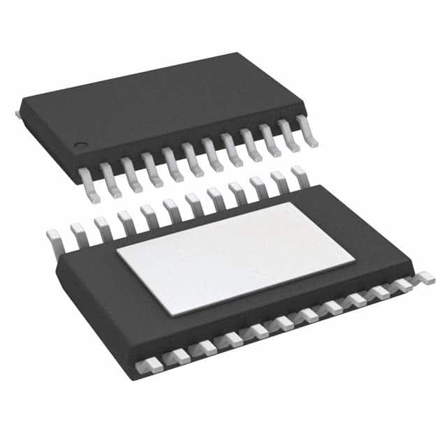
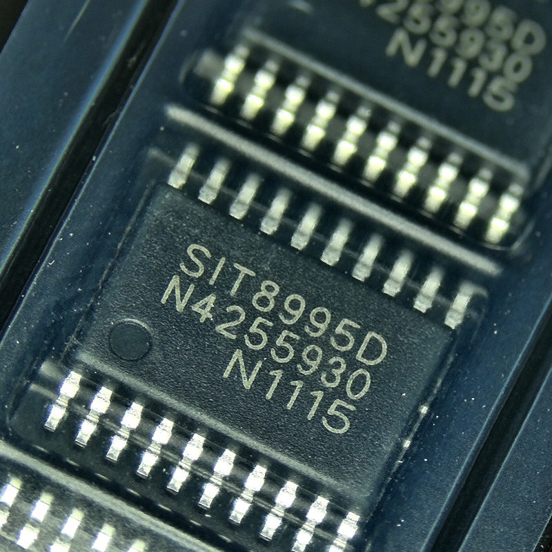
The SIT8995D is supplied in a 20-pin TSSOP package.
TSSOP20 offers a useful balance between compact PCB size and enough pins for multiple cell-sense inputs, charge and discharge controls, balancing functions, current sensing, temperature monitoring, configuration, and supporting circuitry.
When creating the PCB footprint, designers should use the manufacturer's package drawing rather than copying dimensions from a visually similar TSSOP20 component.
Small differences in pad size, pitch assumptions, solder-mask opening, or package body dimensions can affect production yield.
Buying SIT8995D Online
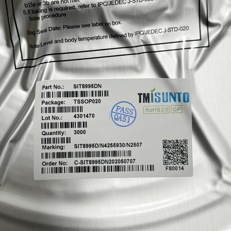
When sourcing TMI SIT8995D, search using the complete part number rather than only "SIT8995."
This matters because the SIT8995 family contains several suffix versions with different voltage and current protection settings.
For purchasing, confirm:
- Part number: SIT8995D
- Brand: TMI
- Manufacturer group: TOLL Microelectronic
- Category: Battery Protection IC
- Cell count: 4S / 5S
- Package: TSSOP20
- Protection threshold version: D
- Lot and traceability information when required
- Packaging quantity
- Distributor or supplier reliability
A lower price should not be the only reason to choose a supplier. Battery protection is a safety-critical function, so part authenticity and traceability can be more important than a small difference in unit cost.
SIT8995D Engineering Insight: Focus on System Behavior, Not Only IC Features
A common mistake in battery design is to treat the protection IC as an isolated component.
In reality, SIT8995D protection performance depends on the complete system.
The sense resistor determines how current translates into detection voltage. MOSFET resistance affects heat and voltage drop. PCB routing changes current-sense accuracy. The NTC position changes the temperature that the IC actually measures. Cell quality changes pack imbalance. Charger behavior affects recovery from protection states.
This leads to a useful rule:
A good battery protection IC cannot correct a poor battery-pack design, but a well-designed battery pack can use the IC's protection functions much more effectively.
For this reason, engineering validation should test the complete assembled battery pack rather than only checking whether the schematic matches the reference circuit.
Recommended SIT8995D Validation Tests
Before production, a SIT8995D-based battery pack should be tested under controlled conditions.
- Increase each cell voltage separately and verify overcharge protection.
- Reduce each cell voltage separately and verify over-discharge protection.
- Test overcharge recovery.
- Test over-discharge recovery.
- Apply controlled discharge overcurrent conditions.
- Test the second overcurrent stage.
- Verify short-circuit protection using safe laboratory equipment.
- Test charging overcurrent detection.
- Test high-temperature charging protection.
- Test low-temperature charging protection.
- Test high-temperature discharge protection.
- Verify cell-balancing operation.
- Verify 4-cell or 5-cell configuration.
- Measure sleep-mode current.
- Test charger reconnection and recovery behavior.
- Repeat important tests at low and high ambient temperatures.
Production testing can then use a smaller set of critical tests derived from the full engineering validation process.
Frequently Asked Questions About SIT8995D
What is SIT8995D?
SIT8995D is a multi-cell lithium battery protection IC from TMI / TOLL Microelectronic. It is designed for four-cell and five-cell Li-Ion or Li-Polymer battery packs.
What category does SIT8995D belong to?
SIT8995D belongs to the Power Management IC category and is more specifically classified as a Battery Management or Battery Protection IC.
Is SIT8995D a BMS chip?
It can be used as the main hardware protection IC inside a 4S or 5S BMS. It provides important BMS protection functions but is not a complete smart BMS with communication, state-of-charge calculation, and battery data logging.
How many cells does SIT8995D support?
It supports four or five series-connected lithium battery cells.
What is the SIT8995D overcharge voltage?
The SIT8995D variant has a listed overcharge detection voltage of 3.75 V per cell.
What is the SIT8995D overcharge recovery voltage?
Its listed overcharge recovery voltage is 3.55 V per cell.
What is the SIT8995D over-discharge voltage?
Its listed over-discharge protection level is 2.2 V per cell.
What is the over-discharge recovery voltage?
The listed recovery level is 2.7 V per cell.
Does SIT8995D support battery balancing?
Yes. The SIT8995 family includes cell-balancing control. The SIT8995D has a listed balance turn-on voltage of 3.515 V.
Does SIT8995D provide temperature protection?
Yes. The device supports charging high-temperature protection, charging low-temperature protection, and discharging high-temperature protection using an external NTC temperature sensor.
Does SIT8995D have short-circuit protection?
Yes. The IC detects a short-circuit condition through its current-sense system and can disable the discharge path through external switching devices.
Is SIT8995D a battery charger IC?
No. It is primarily a battery protection IC. A separate charger circuit is normally required to control battery charging.
Is SIT8995D a fuel gauge?
No. It does not replace a battery fuel-gauge IC used to estimate state of charge or remaining capacity.
What package does SIT8995D use?
SIT8995D uses a TSSOP20 package.
Who makes SIT8995D?
SIT8995D is associated with TMI, a brand of TOLL Microelectronic. TOLL Microelectronic develops analog and mixed-signal integrated circuits.
Final Evaluation of SIT8995D
The SIT8995D is a focused battery safety IC for 4-cell and 5-cell lithium battery packs. Its value comes from combining several important protection functions into one TSSOP20 device, including individual cell-voltage monitoring, charge overvoltage protection, discharge undervoltage protection, two-stage discharge overcurrent detection, charge overcurrent protection, short-circuit protection, temperature monitoring, cell-balancing control, MOSFET management, and low-power sleep operation.
For the SIT8995D version, key listed thresholds include a 3.75 V overcharge detection level, 3.55 V overcharge recovery level, 3.515 V balance turn-on level, 2.2 V over-discharge protection level, and 2.7 V over-discharge recovery level.
Those numbers are more important than the feature list alone. The correct battery protection IC is the one whose thresholds, current-sense behavior, temperature limits, cell count, recovery logic, and external circuit requirements match the real battery cells and application.
From a system-design perspective, the strongest way to use TMI SIT8995D is as an independent hardware safety layer inside a larger BMS architecture. A charger can manage charging, a fuel gauge can estimate battery capacity, and a microcontroller can provide communication and intelligent control, while SIT8995D remains focused on detecting dangerous electrical and thermal conditions.
For designers looking for a 4 cell battery protection IC, 5 cell battery protection IC, Li-ion battery protection IC, Li-polymer battery protector, or compact BMS protection IC, SIT8995D is worth evaluating when its fixed D-version thresholds match the required battery specification.
The final design should always be verified with the current manufacturer datasheet, the selected battery-cell specification, real MOSFETs, actual sensing components, PCB layout, temperature testing, and controlled fault testing before the battery pack enters mass production.