

Microchip Technology
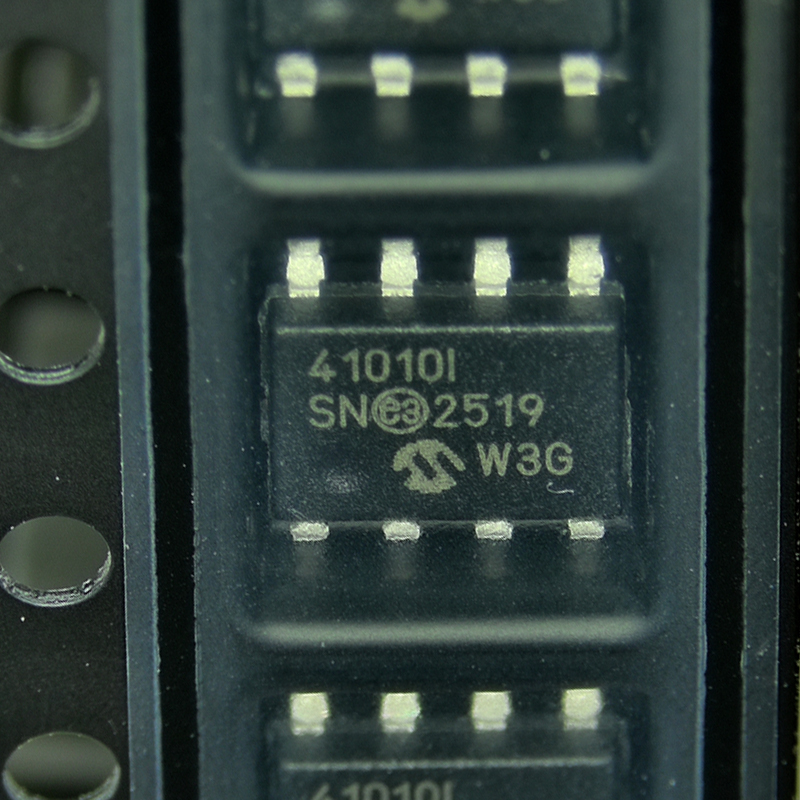
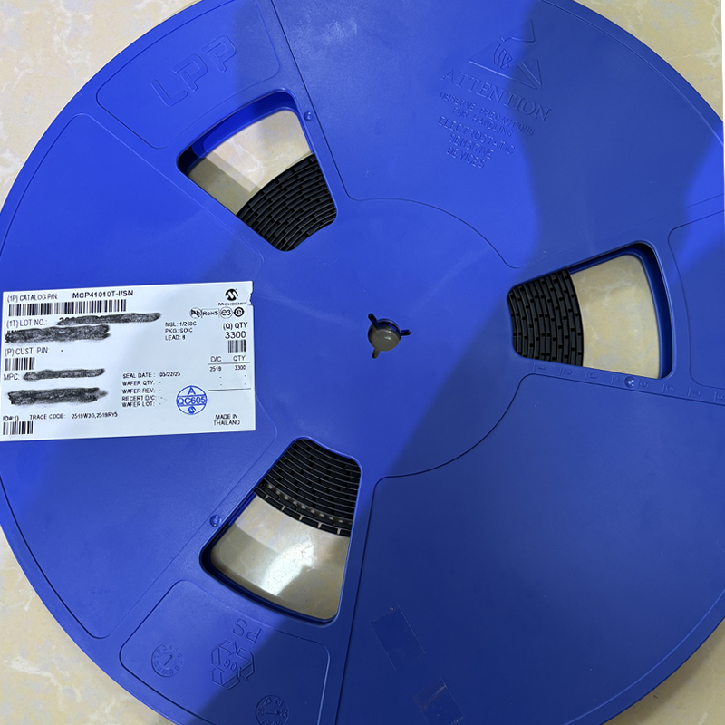
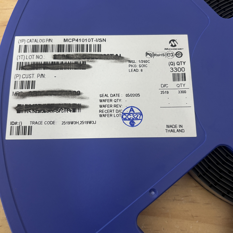
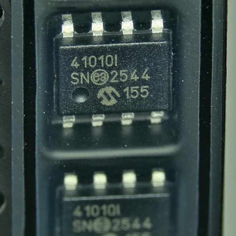
MCP41010T-I/SN
IC DGTL POT 10KOHM 256TAP 8SOIC
Flychip Semiconductor Solutions
20 Years
Your reliable partner for semiconductor solutions. Flychip supports customers from R&D to mass production with electronic component supply, BOM sourcing, PCB, SMT and PCBA services.
- 20+
- Years Component Supply
- BOM
- Multi-Part Sourcing
- PCBA
- PCB / SMT Support
- Part No.:
- MCP41010T-I/SN
- Manufacturer:
- Microchip Technology
- Category:
- Digital Potentiometers
- Package:
- 8-SOIC (0.154", 3.90mm Width)
- Datasheet:
- MCP41010T-I/SN.pdf
- Description:
- IC DGTL POT 10KOHM 256TAP 8SOIC
- Quantity:
-
Quality Control
Supplier review, channel management and product verification before delivery.
-
Global Channels
International chip manufacturer and well-known distributor sourcing network.
-
BOM to Production
Component supply support from R&D prototype to mass production.
-
PCB / SMT / PCBA
Integrated manufacturing support to accelerate product development and delivery.
Product Details
MCP41010T-I/SN Digital Potentiometer Guide: 10kΩ SPI IC, Pinout,
At first sight, the MCP41010T-I/SN may look like one of many small electronic IC chips used on a PCB. Its real value becomes clearer when we look at what it does between the digital and analog parts of a system. A microcontroller sends digital commands through SPI, while the internal resistor network changes an analog resistance or voltage ratio. This simple connection between software and analog circuitry makes the device useful in gain control, signal adjustment, calibration, filters, audio circuits, power-related control loops, instrumentation, and many other embedded products.
For engineers comparing electronics IC chips, the important question is not simply whether a chip has more features. The better question is whether the IC solves the required function with the least circuit complexity. The MCP41010T-I/SN is a good example of this principle. It does one focused job: it provides a digitally controlled 10 kΩ potentiometer with 8-bit resolution and SPI communication.
What Is MCP41010T-I/SN?
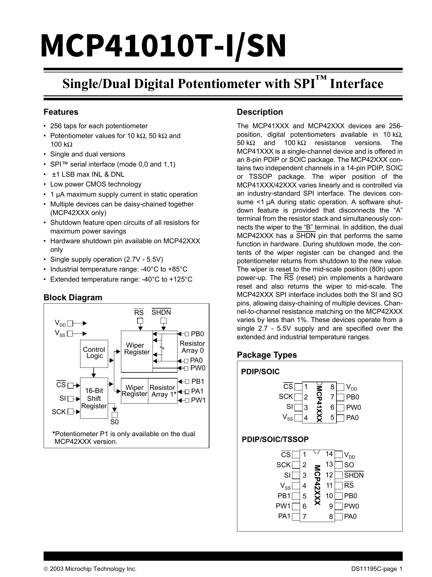
The MCP41010T-I/SN belongs to Microchip's MCP41XXX digital potentiometer family. It contains one digitally controlled resistor network and one movable electronic wiper. Instead of turning a physical shaft, firmware writes an 8-bit value that determines the wiper position.
The device provides 256 possible wiper positions. In a simplified view, code 0 places the wiper near one end of the resistor string, while progressively larger codes move it toward the other end. This allows a processor to adjust an analog circuit without requiring a motorized potentiometer, relay network, or manual adjustment.
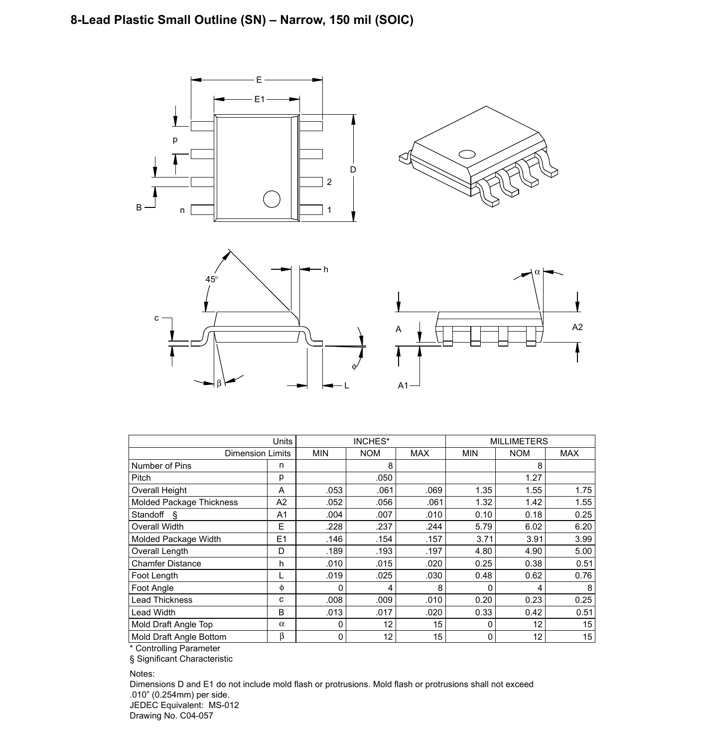
The part number itself also tells designers useful information. The MCP41010 identifies the 10 kΩ single-channel member of the family. The industrial version is designed for operation across the industrial temperature range. The SN package is an 8-lead SOIC package suitable for surface-mount assembly, while the T ordering form is supplied for tape-and-reel production handling.
This packaging detail can matter more than it first appears. Prototype engineers usually focus on electrical specifications, but purchasing and manufacturing teams also care about feeder compatibility, automated placement, package size, moisture handling, and production quantity. Therefore, selecting MCP41010T-I/SN is both an electrical and manufacturing decision.
MCP41010T-I/SN Key Specifications
| Parameter | MCP41010T-I/SN |
|---|---|
| Device Type | Digital Potentiometer |
| Number of Channels | 1 |
| Nominal Resistance | 10 kΩ |
| Resolution | 8-bit |
| Wiper Positions | 256 |
| Digital Interface | SPI |
| Supply Voltage | 2.7 V to 5.5 V |
| Package | 8-pin SOIC |
| Temperature Class | Industrial |
| Operating Temperature | -40°C to +85°C |
| Memory Type | Volatile |
| Power-Up Wiper Position | Mid-scale |
| Nominal Resistance Type | Linear |
| Packaging | Tape and Reel |
One specification deserves special attention: volatile memory. The MCP41010T-I/SN does not permanently save its last wiper setting when power is removed. After power-up, the wiper returns to its defined mid-scale state. Firmware should therefore configure the desired value during system initialization.
This is not necessarily a disadvantage. In many embedded products, a predictable startup state is preferable to remembering an unknown previous setting. For example, an amplifier can start at a safe gain, or a control circuit can begin from a known midpoint before software applies calibration values stored elsewhere.
How the MCP41010T-I/SN Works
Understanding the internal idea is easier if we first ask, what is integrated chip technology used for? An integrated chip combines many electronic elements inside one semiconductor package so that a larger circuit function can be implemented with fewer external parts.
In the MCP41010T-I/SN, the key integrated elements are a resistor array, an electronic wiper selection system, control logic, an 8-bit wiper register, and an SPI-compatible digital interface. Together they behave like a potentiometer whose shaft has been replaced by a software command.
The three analog terminals are commonly identified as PA0, PB0, and PW0. PA0 and PB0 act like the two ends of a normal potentiometer. PW0 is the wiper terminal. The SPI interface determines where PW0 connects along the internal resistor network.
This creates two common design modes.
- Potentiometer mode: PA0 and PB0 are connected across a voltage, while PW0 produces an adjustable divided voltage.
- Rheostat mode: the wiper and one resistor endpoint are used to create a programmable resistance.
The distinction is important because the chip is not simply a digital resistor with unlimited use. Terminal voltage limits, wiper resistance, current limits, signal bandwidth, power dissipation, and the surrounding analog circuit must all be considered during design.
MCP41010T-I/SN Pinout
| Pin | Name | Function |
|---|---|---|
| 1 | CS | SPI chip select input |
| 2 | SCK | SPI serial clock input |
| 3 | SI | SPI serial data input |
| 4 | VSS | Ground |
| 5 | PA0 | Potentiometer terminal A |
| 6 | PW0 | Potentiometer wiper terminal |
| 7 | PB0 | Potentiometer terminal B |
| 8 | VDD | Positive supply voltage |
The compact pinout is one reason this part is easy to integrate into an electronic components PCB design. Only three SPI control signals are required from the microcontroller: chip select, clock, and serial data input. The remaining pins are power and analog potentiometer connections.
Why SPI Control Is Useful
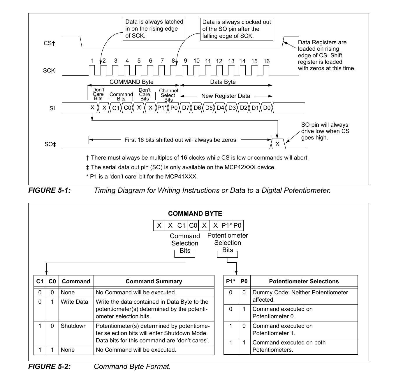
SPI is widely used between microcontrollers and electronic components because it is simple, fast, and easy to implement in firmware. A typical microcontroller already includes hardware SPI, so the MCP41010T-I/SN can often be added without complicated communication circuitry.
The processor selects the device through CS, sends command and data information through SI, and uses SCK to clock the information into the chip. The requested value is then transferred to the internal wiper register.
For a designer, this means resistance can become part of the software control strategy. A firmware routine can increase gain, reduce signal level, change a calibration point, or compensate for changing operating conditions without a user physically touching the circuit.
This capability is especially valuable when the electronics are inside a sealed enclosure or installed in a location that is difficult to access.
The Real Meaning of 256 Steps
The MCP41010T-I/SN has an 8-bit wiper register, producing 256 wiper positions. It may be tempting to divide 10,000 Ω by 256 and assume that every step produces an ideal resistance change of approximately 39 Ω.
That calculation is useful for a quick estimate, but a real circuit requires more thought.
The total end-to-end resistance has manufacturing tolerance, and the internal electronic wiper also has resistance. Therefore, the exact resistance measured between the wiper and an endpoint is not simply the ideal resistor-string value.
This leads to an important design insight: a digital potentiometer should usually be selected by looking at the whole transfer function of the circuit, not only by calculating the theoretical resistance per code.
For example, if the MCP41010T-I/SN is used to adjust an operational amplifier gain, the engineer should calculate the actual gain range, required resolution, resistor tolerance, wiper contribution, temperature behavior, and amplifier characteristics together. That produces a much more realistic result than assuming that 256 positions automatically mean 256 perfectly equal system outputs.
MCP41010T-I/SN as a Bridge Between Digital and Analog Electronics
Many electron devices and circuits contain both digital and analog sections. Sensors produce analog signals. Microcontrollers process digital information. Amplifiers, filters, power circuits, and interfaces frequently sit between these two worlds.
The MCP41010T-I/SN is useful because it lets digital firmware modify an analog circuit parameter directly.
Consider an analog amplifier whose gain must change according to sensor conditions. One approach is to use fixed resistors and several analog switches. Another is to use a DAC and redesign the control topology. A digital potentiometer may offer a simpler solution when its voltage, resistance, accuracy, and bandwidth characteristics fit the application.
That is why digital potentiometers continue to be useful even when modern microcontrollers contain ADCs, DACs, PWM outputs, and many other peripherals. The digital potentiometer performs a different job: it behaves much more directly like an adjustable resistor network.
Common MCP41010T-I/SN Circuit Applications
1. Programmable Amplifier Gain
One of the most useful applications is adjustable amplifier gain. The MCP41010T-I/SN can form part of the feedback network around an operational amplifier, allowing firmware to change gain according to the operating mode.
This can be useful in sensor interfaces where a small signal needs more gain than a large signal. Instead of building several separate gain stages, software can select an appropriate resistance setting.
2. Audio Volume and Level Control
A digital potentiometer can provide electronically controlled signal attenuation in certain audio designs. A processor can translate button presses, encoder movement, stored presets, or remote commands into wiper settings.
However, audio designers should not look only at the 10 kΩ value. Signal voltage range, distortion requirements, wiper resistance, noise, bandwidth, step behavior, and circuit topology also matter.
3. Sensor Calibration
Sensors often require offset or gain correction. During production testing, calibration software can measure a sensor output and choose an MCP41010T-I/SN code that brings the complete system closer to its target value.
The final calibration code can then be stored in the microcontroller's nonvolatile memory. Every time the product starts, firmware reads that value and programs the digital potentiometer.
This approach is particularly useful because the MCP41010 itself is volatile. The calibration information does not have to be permanently stored inside the potentiometer when the controller already has suitable nonvolatile storage.
4. Programmable Filters
Resistance is a major factor in many active and passive filter equations. Replacing an appropriate resistor with a digital potentiometer can provide digitally adjustable filter characteristics.
Designers must still evaluate the required frequency range. The MCP41010T-I/SN is an analog component as well as a digital component, so parasitic capacitance and resistance affect high-frequency behavior.
5. LCD Contrast and Bias Adjustment
Some display systems require an adjustable bias or contrast voltage. A digital potentiometer can allow firmware to adapt that voltage according to user preference, operating condition, or calibration requirements.
6. Instrumentation
Measurement equipment frequently needs adjustable gain, offset, or reference levels. The MCP41010T-I/SN provides repeatable digital settings without requiring a mechanical trim potentiometer to remain accessible after assembly.
7. Communication Circuits
Certain communication and interface circuits need adjustable signal levels or impedance-related control. A digital potentiometer can be considered where its electrical limits match the signal path.
Digital Potentiometer vs Mechanical Potentiometer
| Feature | MCP41010T-I/SN Digital Pot | Mechanical Potentiometer |
|---|---|---|
| Control | Firmware through SPI | Manual rotation |
| Remote Adjustment | Easy | Difficult without additional hardware |
| Repeatable Setting | Digital code based | Depends on physical position |
| Mechanical Wear | No mechanical wiper movement | Mechanical wear is possible |
| Automatic Calibration | Suitable | Usually manual |
| Power-Off Memory | Volatile on MCP41010 | Physical position remains |
| Resolution | 256 discrete settings | Continuous mechanical movement |
| MCU Integration | Direct SPI control | Requires extra sensing or motorization |
Neither solution is automatically better. A mechanical potentiometer is excellent when a human directly controls the setting and a continuous physical interface is desirable. The MCP41010T-I/SN is more attractive when resistance must be changed automatically, remotely, repeatedly, or according to software logic.
MCP41010T-I/SN and Integrated Circuit Design
When people search for electronic IC chips or electronics IC chips, they may imagine processors, memory, or complex digital logic. Yet integrated circuits also include highly focused analog and mixed-signal devices.
The MCP41010T-I/SN demonstrates why integration is useful. A discrete implementation of an electronically adjustable resistor could require many resistors, analog switches, control lines, and additional PCB space. Integrating the resistor network and switch control into one IC greatly simplifies the design.
This also explains the answer to the common search question what is integrated chip. In practical terms, an integrated chip places a collection of electronic structures onto one semiconductor device to perform a useful function. In the MCP41010T-I/SN, that function is a digitally controlled analog potentiometer.
The concept is related to other specialized integrated circuits but should not be confused with them. For example, a PMIC power management integrated circuit manages functions such as voltage regulation, sequencing, power distribution, or battery-related control. A digital potentiometer instead provides adjustable resistance or voltage division. Both are integrated circuits, but they solve very different design problems.
PCB Design Considerations for MCP41010T-I/SN
A correct schematic is only the beginning of a reliable design. PCB layout has a direct effect on analog performance, especially when digital clock signals share the same board with low-level analog signals.
Place the Bypass Capacitor Close to the Device
A local bypass capacitor between VDD and VSS helps reduce supply disturbance. It should be placed physically close to the MCP41010T-I/SN power pins, with short connections.
Keep SPI Clock Away From Sensitive Analog Nodes
The SCK line changes rapidly and can couple unwanted digital energy into nearby analog traces. Keep the clock path short and avoid routing it parallel to sensitive wiper or amplifier input traces for unnecessary distances.
Use a Clean Ground Strategy
Digital return currents should not be allowed to create unwanted voltage drops in a sensitive analog ground path. The best layout depends on the full board architecture, but designers should think about current return paths instead of treating every ground connection as electrically identical.
Keep Analog Connections Short
The PA0, PB0, and PW0 traces should be kept reasonably short, especially when the circuit handles high-impedance or noise-sensitive signals.
Check the Startup State
Because the wiper starts at mid-scale after power-up, the complete circuit should remain safe at that value. Firmware can quickly load another setting, but hardware should not rely on software being active at the exact instant power appears.
A Useful Design Insight: Do Not Treat MCP41010T-I/SN Like an Ideal Resistor
One of the most common design mistakes with digital potentiometers is treating them as perfect digitally programmable resistors.
A real device includes resistor tolerance, wiper resistance, code-dependent behavior, temperature effects, voltage restrictions, current restrictions, parasitic capacitance, and finite bandwidth. These factors may be small in one application and important in another.
For example, a calibration circuit operating slowly at low frequency may care mostly about resistance tolerance and resolution. An audio design may care more about signal range, noise, distortion, and transitions between codes. A filter may care about bandwidth and parasitic capacitance.
The correct engineering question is therefore not:
"Is MCP41010T-I/SN accurate?"
A better question is:
"Are the MCP41010T-I/SN error sources small enough for the accuracy required by my complete circuit?"
That change in thinking often separates a successful design from one that works only in a simple prototype.
How MCP41010T-I/SN Fits Into Modern Electronic Components
Modern electronic components are increasingly controlled by software. Power converters use digital configuration, sensors include internal registers, amplifiers have programmable modes, and communication devices use serial control buses.
The MCP41010T-I/SN fits naturally into this architecture because it turns an analog adjustment into a programmable system variable.
Imagine an environmental sensor product. The analog front end may need different gain at different sensor levels. A microcontroller can measure the ADC result, select an appropriate gain setting, send a new value to the MCP41010T-I/SN, wait for the signal to settle, and then make another measurement.
In this case, the digital potentiometer is not just another component on the board. It becomes part of the control algorithm.
Using MCP41010T-I/SN With Microcontrollers
Most modern microcontrollers include an SPI peripheral, making communication relatively simple.
A typical initialization sequence may follow this logic:
- Configure the microcontroller's SPI interface.
- Configure the CS pin as a digital output.
- Keep CS inactive while the system starts.
- Select the MCP41010T-I/SN.
- Send the required command information.
- Send the desired 8-bit wiper value.
- Release CS.
- Repeat whenever a new resistance setting is needed.
The exact SPI timing and command format should always follow the manufacturer's current datasheet. This is important because a digital potentiometer may appear simple, but incorrect SPI mode, timing, or command bits can prevent reliable operation.
Choosing the Right Wiper Code
For some applications, the software can directly map a user setting to a wiper code. A volume control could translate a level value into a corresponding digital potentiometer command.
More precise applications should use a better method.
For example, an instrument can measure several calibration points during manufacturing and store correction data in nonvolatile memory. The firmware can then use a lookup table, linear correction equation, or interpolation algorithm to select the most useful MCP41010T-I/SN code.
This approach recognizes an important fact: the relationship between wiper code and the final system output is not always perfectly linear, even though the resistor array itself is designed for linear adjustment.
MCP41010T-I/SN Versus a DAC
A digital potentiometer and a digital-to-analog converter can both create digitally controlled analog behavior, but they are not interchangeable.
A DAC generates an analog voltage or current from a digital code. The MCP41010T-I/SN instead changes the position of a wiper on a resistor network.
If the design needs a precise generated reference voltage, a DAC may be more suitable. If the goal is to replace or automate a resistor or potentiometer inside an existing analog topology, a digital potentiometer can be much simpler.
The choice should therefore be based on circuit function rather than simply comparing resolution numbers.
MCP41010T-I/SN Versus a PMIC Power Management Integrated Circuit
The phrase pmic power management integrated circuit often appears when engineers research analog ICs. A PMIC may control regulators, power rails, sequencing, charging, monitoring, or other power functions.
The MCP41010T-I/SN is not a PMIC. However, it can sometimes appear inside a larger power-related design when adjustable resistance is required by a feedback or control circuit.
When considering such an application, engineers must verify that the digital potentiometer's terminal voltages, current, resistance range, failure behavior, startup state, and overall architecture are suitable. It should not simply be inserted into a regulator feedback network without checking the consequences.
Using MCP41010T-I/SN on an Integrated Circuit Card or Control Board
An integrated circuit card or embedded control PCB may contain a microcontroller, voltage regulators, sensors, communication devices, amplifiers, connectors, and many passive components. The MCP41010T-I/SN can serve as a small configurable analog element inside this larger architecture.
Its 8-pin SOIC package makes it relatively easy to place near the analog circuit that it controls while the SPI signals connect back to the processor.
This placement can be better than locating the potentiometer near the processor simply because SPI originates there. In many designs, keeping the sensitive analog path short is more important than saving a small amount of digital trace length.
Electronic Components PCB Integration Checklist
- Confirm the 10 kΩ resistance range suits the application.
- Check that 256 positions provide enough control resolution.
- Verify all analog terminal voltages stay within allowed limits.
- Check wiper current and power requirements.
- Confirm SPI voltage levels are compatible with the controller.
- Use the correct SPI mode and timing.
- Add local power-supply decoupling.
- Keep noisy digital traces away from sensitive analog nodes.
- Design for the mid-scale power-up position.
- Reprogram the required value after every power cycle.
- Verify the SOIC footprint before manufacturing.
- Confirm the exact MCP41010T-I/SN ordering code on the BOM.
- Validate the circuit over temperature and supply variation.
- Test real production boards rather than relying only on simulation.
Buying MCP41010T-I/SN and Other Online Components
Engineers frequently search for online components only after a schematic has already been designed. A better approach is to think about sourcing while selecting the part.
For MCP41010T-I/SN, verify the complete manufacturer part number rather than searching only for MCP41010. Closely related ordering codes may use different packages, temperature grades, or packing methods.
Searches such as electronic component stores near me can be useful for quick prototypes, but production purchasing usually requires stronger checks. Confirm the manufacturer, exact suffix, traceability, packaging, moisture handling requirements, date information when relevant, minimum order quantity, and authorized distribution status.
The same rule applies when using distributor searches or phrases such as master electronics online components, online components login, or online components.com. The search platform is only the beginning. The manufacturer's part number and technical documentation remain the reference points for engineering decisions.
This is especially important for electronics IC chips because two parts with almost identical names can differ in package, operating temperature, reel format, or electrical characteristics.
How to Avoid Wrong-Part Purchases
A simple purchasing workflow can prevent many problems.
- Start with the manufacturer's complete part number: MCP41010T-I/SN.
- Confirm the manufacturer is Microchip Technology.
- Verify 10 kΩ resistance.
- Verify single-channel operation.
- Verify the 8-pin SOIC package.
- Check the required temperature range.
- Check tape-and-reel requirements for production.
- Compare the distributor listing with the official datasheet.
- Keep approved alternates separate from the primary BOM item.
This may seem basic, but BOM mistakes are expensive because they often appear late in the manufacturing process.
Should You Use MCP41010T-I/SN in a New Design?
The MCP41010 family remains useful when a project specifically needs a simple 10 kΩ, single-channel, SPI-controlled, volatile digital potentiometer.
However, engineers starting a completely new design should also compare newer pin-compatible or functionally similar devices from the manufacturer. Newer families may offer additional memory options, different interfaces, lower power characteristics, improved specifications, or better long-term product alignment.
This does not make the MCP41010T-I/SN a poor device. It simply reflects good component engineering: never choose a part based only on familiarity. Compare current alternatives before freezing the BOM, especially for products expected to remain in production for many years.
When MCP41010T-I/SN Is a Strong Choice
MCP41010T-I/SN is particularly attractive when your design needs:
- A 10 kΩ digital potentiometer
- One programmable channel
- 256 wiper positions
- SPI control
- 2.7 V to 5.5 V operation
- An 8-pin surface-mount package
- Industrial temperature capability
- Software-controlled calibration
- Repeatable analog settings
- A simple replacement for a manually adjusted potentiometer
It may be less suitable when the application requires nonvolatile wiper memory, a different resistance value, more channels, extremely high analog precision, very high signal bandwidth, or a control interface other than SPI.
MCP41010T-I/SN in Automated Calibration Systems
Automated calibration is one of the most interesting uses of the MCP41010T-I/SN because it shows why digitally controlled analog components are valuable.
Imagine a product with a sensor amplifier. Component tolerances cause each assembled board to produce a slightly different gain. A production test fixture applies a known input and measures the output. Firmware then adjusts the MCP41010T-I/SN until the result falls within the required range.
The selected code is saved in the microcontroller's flash or EEPROM. When the product is powered again, the processor loads the stored calibration value and writes it to the digital potentiometer.
This removes the need for a technician to turn a physical trimmer on every board. It also makes calibration data measurable, traceable, and repeatable.
A Broader View of Electronic IC Chips and Integration
The history of electronic IC chips is largely a history of moving more useful functions into smaller, more predictable packages. But integration does not always mean creating a more complicated chip.
Sometimes the best integrated circuit takes a simple physical function and makes it controllable.
The MCP41010T-I/SN does exactly that. A traditional potentiometer gives a person physical control over resistance. The digital potentiometer gives software control over essentially the same design concept.
This is an important lesson when selecting electronic components: integration should simplify the system, not merely increase the number of features on the datasheet.
Understanding Search Intent Around Electronic Components
Technical search engines sometimes combine very different types of queries. A person searching for the MCP41010T-I/SN may also see educational topics such as determine the x component of the force on the electron or determine the x-component of the force on the electron.
Those phrases belong to physics problems dealing with forces, vectors, electric fields, or charged particles. They are fundamentally different from a component-selection query for the MCP41010T-I/SN.
This distinction matters in engineering research. Searching for electron devices and circuits may lead to theory, textbooks, semiconductor physics, and practical circuit design, while searching for a specific manufacturer part number should lead to datasheets, package information, reference circuits, availability, and compliance data.
For a component such as MCP41010T-I/SN, the exact manufacturer part number should therefore be treated as the strongest search signal.
Digital Potentiometers and Future Circuit Integration
Discussions about semiconductor integration often focus on processors and artificial intelligence, but small mixed-signal components remain essential. Sensors, industrial controllers, medical instruments, test equipment, smart appliances, communication products, and embedded systems still require simple ways to control analog behavior.
Events such as a custom integrated circuits conference may discuss advanced semiconductor architectures, specialized IC design, mixed-signal integration, and new manufacturing approaches. At the board level, however, engineers still need practical components that solve clearly defined problems.
The MCP41010T-I/SN represents this practical side of integration. It does not attempt to replace the entire analog circuit. Instead, it gives software one precise control point inside that circuit.
That architecture can be more flexible than creating a custom IC when production volume does not justify custom silicon.
MCP41010T-I/SN Design Example: Adjustable Sensor Gain
Consider a sensor whose signal changes from very small values to much larger values. A fixed-gain amplifier must compromise between sensitivity at the low end and saturation at the high end.
Adding the MCP41010T-I/SN to an appropriate amplifier feedback network can allow several software-selectable gain regions.
A simplified control process could work like this:
- Start the digital potentiometer at a safe gain setting.
- Read the sensor through the ADC.
- If the signal is very small, select a higher-gain wiper code.
- Allow the analog circuit to settle.
- Measure again.
- If the signal approaches the ADC limit, reduce gain.
- Record the selected gain with the measurement result.
This creates a basic programmable-gain measurement system without requiring a large number of switched resistors.
The concept sounds simple, but robust implementation also needs hysteresis, settling time, error handling, calibration, input protection, and analysis of the amplifier's stability over the full resistance range.
MCP41010T-I/SN Design Example: Factory Calibration
A second example is a product that needs a specific output voltage despite resistor and sensor tolerances.
During production testing, the controller can sweep several MCP41010T-I/SN codes while test equipment measures the result. Software can identify the best code and store it as the unit's calibration value.
This strategy offers three major benefits.
- Speed: calibration can be automated.
- Repeatability: every adjustment corresponds to a digital number.
- Traceability: the selected calibration code can be recorded with production data.
These advantages often matter more than the simple fact that the IC contains a 10 kΩ resistor network.
Practical Limitations Engineers Should Remember
The MCP41010T-I/SN is useful, but it should not be treated as a universal replacement for every potentiometer.
It Is Volatile
The wiper value must be restored after power cycling if the application needs a specific startup setting.
It Has Discrete Steps
The device provides 256 settings, not a continuously variable resistance.
The Wiper Is Not Ideal
The electronic switch forming the wiper adds resistance. This becomes especially important when operating close to one end of the resistor string.
Analog Voltage Limits Matter
Do not assume the analog terminals can handle signals outside the device supply range. The datasheet must be checked against the real signal conditions.
Current Is Limited
A digital potentiometer is intended for signal and control functions, not for replacing a high-power variable resistor.
Frequency Response Is Finite
The internal resistor network and parasitic capacitance create frequency-dependent behavior. High-frequency designs need closer analysis than slow calibration circuits.
Frequently Asked Questions About MCP41010T-I/SN
What is MCP41010T-I/SN?
MCP41010T-I/SN is a Microchip single-channel digital potentiometer with a nominal 10 kΩ resistance, 256 wiper positions, SPI control, and an 8-pin SOIC package.
Is MCP41010T-I/SN an electronic IC chip?
Yes. It is a mixed-signal integrated circuit that combines digital SPI control with an analog resistor network and electronic wiper.
How many steps does MCP41010T-I/SN have?
It provides 256 wiper positions controlled by an 8-bit register.
What resistance is MCP41010T-I/SN?
Its nominal end-to-end potentiometer resistance is 10 kΩ.
What interface does MCP41010T-I/SN use?
It uses an SPI-compatible serial interface.
What is the MCP41010T-I/SN supply voltage?
The device operates from a single supply in the 2.7 V to 5.5 V range.
Does MCP41010T-I/SN remember its wiper value after power is removed?
No. It uses a volatile wiper register. Firmware should program the required value again during startup.
What happens to the wiper at power-up?
The MCP41010 family initializes the wiper to its mid-scale position when powered.
Can MCP41010T-I/SN replace a mechanical potentiometer?
In many low-power electronic circuits, yes, provided the application's voltage, current, resistance, accuracy, and frequency requirements remain inside the digital potentiometer's operating limits.
Can MCP41010T-I/SN be used as a variable resistor?
Yes. It can be configured in a rheostat-style connection using the wiper and an appropriate endpoint of the internal resistor network.
Can MCP41010T-I/SN control amplifier gain?
Yes, it can be used in suitable operational-amplifier feedback networks to provide digitally adjustable gain. The complete circuit should be analyzed for stability, resistance range, wiper effects, and signal limits.
Is MCP41010T-I/SN suitable for PCB production?
Yes. Its 8-pin SOIC surface-mount package and tape-and-reel ordering format make it suitable for automated PCB assembly.
What should I check before buying MCP41010T-I/SN online?
Verify the complete manufacturer part number, package, resistance value, temperature grade, packaging format, authorized supply source, documentation, and production requirements rather than choosing an item only because its short description says "MCP41010."
Final Evaluation
The MCP41010T-I/SN is a good example of how a small integrated circuit can simplify a much larger electronic system. It combines a 10 kΩ resistor network, 256 programmable positions, digital control logic, and an SPI interface inside a compact 8-pin SOIC package.
Its greatest advantage is not simply that it replaces a mechanical potentiometer. Its greater value is that it turns resistance into something firmware can control.
That capability can enable automatic calibration, programmable amplifier gain, adjustable filters, instrumentation control, sensor optimization, remote configuration, signal-level adjustment, and other mixed-signal functions.
For designers researching electronic IC chips, electronics IC chips, electronic components, online components, or ways to improve electronic components PCB integration, the MCP41010T-I/SN is worth understanding because it shows how digital and analog design can work together without excessive circuit complexity.
The main engineering lesson is equally important: select the device as part of a complete circuit rather than looking at its 10 kΩ value or 256-step specification in isolation. Check startup behavior, resistance tolerance, wiper resistance, voltage limits, signal bandwidth, PCB layout, SPI timing, temperature range, sourcing, and long-term component strategy.
When those requirements match the application, mcp41010t i sn can provide a compact, predictable, and easy-to-control solution for software-adjustable analog circuits.
Flychip Advantage
From Component Sourcing to Production Delivery
Flychip has been providing electronic components to global customers for 20 years. We combine component supply, BOM services, PCB, SMT and PCBA support to help customers accelerate product development and delivery.
-
R&D Support
Fast sourcing support for prototype development, sample validation and early-stage engineering needs.
-
BOM Services
Multi-line BOM matching with component supply, alternative suggestions and procurement follow-up.
-
Mass Production
Stable supply coordination for production preparation, batch delivery and long-term purchasing needs.
-
Experienced Team
Over 15 years of channel management, quality control, sales management and organization management experience.
MCP41010T-I/SN Technical Information
- Specifications
- FAQ
- Hot Sale
- Related Products
Specifications
- Product Attributes
- Attribute Value
- Manufacturer:
- Microchip Technology
- Series:
- -
- Package/Case:
- 8-SOIC (0.154", 3.90mm Width)
- Packaging:
- Tape & Reel (TR)
- Product Status:
- Active
- Programmable:
- Not Verified
- Taper:
- Linear
- Configuration:
- Potentiometer
- Number of Circuits:
- 1
- Number of Taps:
- 256
- Resistance (Ohms):
- 10k
- Interface:
- SPI
- Memory Type:
- Volatile
- Voltage - Supply:
- 2.7V ~ 5.5V
- Features:
- -
- Tolerance:
- ±20%
- Temperature Coefficient (Typ):
- 800ppm/°C
- Mounting Type:
- Surface Mount
- Grade:
- -
- Qualification:
- -
- Supplier Device Package:
- 8-SOIC
- Operating Temperature:
- -40°C ~ 85°C
- Resistance - Wiper (Ohms) (Typ):
- 73
FAQ
1. How to order MCP41010T-I/SN on Flychip?
You can submit an RFQ directly on this page. Our sales team will review your quantity, delivery requirements and target price, then reply with a quotation as soon as possible.
2. How does Flychip verify the quality of MCP41010T-I/SN?
We work with qualified channels including international chip manufacturers and well-known distributors. Our team pays close attention to supplier review, traceability, product condition and quality control.
3. Are the price and inventory of MCP41010T-I/SN updated in real time?
Inventory and prices of electronic components may fluctuate frequently. The displayed data is for reference, and the final quotation will be confirmed by our sales team.
4. What payment methods are accepted?
Wire Transfer, PayPal, Alipay, WeChat, Credit Card, Western Union, MoneyGram and Escrow may be supported depending on the order and region.
5. How is shipping arranged?
We can arrange international shipping through DHL, UPS, FedEx, TNT and other logistics channels. Tracking information will be provided after shipment.
6. What is the return or replacement process for MCP41010T-I/SN?
Please contact our sales team within the specified period if there are quantity differences, wrong items, or clear external defects. The product should remain unused and in its original packaging.
7. Can I request technical support for MCP41010T-I/SN?
Yes. You can contact us for datasheet, package details, pin information and sourcing assistance related to MCP41010T-I/SN.
Hot Sale
MCP41010T-I/SN
HLK-RM08K MT7688 UART-to-Ethernet and WiFi Gateway Module
MLCC-SAFETY-2-KIT
LM358D
HLK-RM08K MT7688 Industrial WiFi Gateway Serial to Ethernet Module
HLK-RM08K Module: MT7688 Industrial WiFi Router Gateway for Serial Ethernet Applications
76889440220
0825028
HLK-RM08K Module: Industrial WiFi Router Gateway for Serial Ethernet Applications
MAX4062EUB+T
HLK-RM08K MT7688AN Module: Industrial WiFi Router Gateway for Serial Ethernet Applications
CR2032
LR44
TEST2600
test02
MMBTA92LT1G
SS8050
CAP200DG-TL
ATSHA204A-MAHDA-T
ATSHA204A-SSHDA-T
ATSHA204A-STUCZ-T
3SM222KMT1KA-P
MAX4062EUB+
VW3A8306RC
V5.5MLA0603NH
PMD2001D,115
L78L05ABUTR
ACC-140-0633-00
SMT-R005-0.5
RFPD3220
Related Products
-
-
MCP4018T-103E/LT
Microchip Technology
-
-
MCP4018T-503E/LT
Microchip Technology
-
-
MCP4011T-103E/SN
Microchip Technology
-
-
MCP4018T-104E/LT
Microchip Technology
-
-
MCP4017T-503E/LT
Microchip Technology
-
-
MCP4018T-502E/LT
Microchip Technology
-
-
MCP4017T-103E/LT
Microchip Technology
-
-
MCP4531T-103E/MF
Microchip Technology
-
-
MCP4021T-202E/SN
Microchip Technology
-
-
MCP4023T-103E/CH
Microchip Technology
-
-
MCP4022T-503E/CH
Microchip Technology
-
-
MCP4551T-502E/MS
Microchip Technology
MCP41010T-I/SN Sourcing & Technical Support
MCP41010T-I/SN is supplied by Microchip Technology. This page provides key purchasing information including manufacturer, package, datasheet, stock reference, price reference and RFQ support.
As your reliable partner for semiconductor solutions, Flychip supports customers from research and development to mass production with electronic component supply, BOM sourcing, PCB, SMT and PCBA solutions.
Our sourcing partners include international chip manufacturers and well-known distributors. With rich experience in channel management, quality control and sales management, Flychip helps customers accelerate product development and delivery.
- Part Number
- MCP41010T-I/SN
- Manufacturer
- Microchip Technology
- Package
- 8-SOIC (0.154", 3.90mm Width)
- Category
- Digital Potentiometers
Quick RFQ Send your inquiry and our sales team will respond quickly.
Submitting...
Please wait while we submit your inquiry.
Tips
Please check your information and try again.