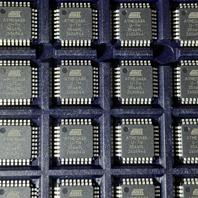


ATMEGA8A-AUR 8-Bit AVR Microcontroller: Specs, Design & Applications
A detailed technical guide to the ATMEGA8A-AUR 8-bit AVR microcontroller, including memory, ADC, timers, communication, PCB design, industrial applications, ATMEGA8A-AUR vs ATMEGA8A-AU differences, tape-and-reel sourcing, and practical component selection.
ATMEGA8A-AUR at a Glance
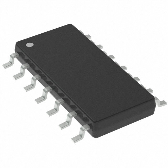
ATMEGA8A-AUR is the Tape & Reel ordering version of the ATmega8A 8-bit AVR microcontroller in a 32-lead TQFP package. It provides 8 KB Flash, 1 KB SRAM, 512 bytes EEPROM, 23 programmable I/O lines, an 8-channel 10-bit ADC in the TQFP package, timers, PWM, USART, SPI and TWI. The key difference from ATMEGA8A-AU is the production packaging format, not the MCU's core electrical function.
The ATMEGA8A-AUR is a compact 8-bit AVR microcontroller designed for embedded products that need predictable control, useful analog functions, standard serial communication, and practical production packaging. It combines 8 KB of programmable Flash memory, 1 KB of SRAM, 512 bytes of EEPROM, 23 programmable I/O lines, timers, PWM, ADC capability, USART, SPI, and a two-wire serial interface.
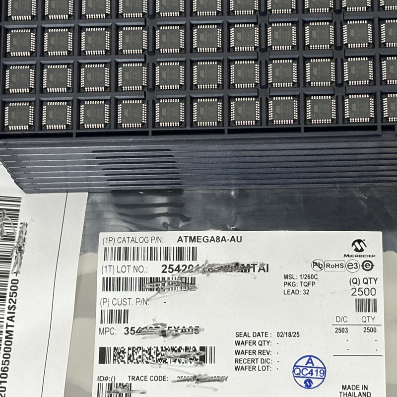
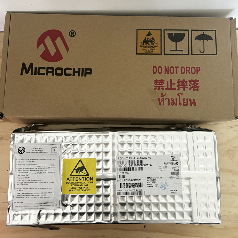
What makes ATMEGA8A-AUR especially important for purchasing and manufacturing teams is the final R in its ordering code. ATMEGA8A-AUR and ATMEGA8A-AU use the same ATmega8A device and the same 32-lead TQFP package, but the AUR ordering option is supplied in Tape & Reel packaging. That difference matters when parts are prepared for automated SMT assembly.
In other words, ATMEGA8A-AUR should not be treated as a completely different microcontroller from ATMEGA8A-AU. The difference is mainly a production and logistics detail rather than a new CPU architecture or different memory configuration.
What Is ATMEGA8A-AUR?
The ATMEGA8A-AUR is an ordering version of the Microchip ATmega8A family, a low-power 8-bit microcontroller based on the AVR RISC architecture. The processor is designed around a simple and efficient instruction set, allowing many instructions to complete in one clock cycle.
The device can operate at frequencies up to 16 MHz and provides performance suitable for a broad range of embedded control tasks. It is not intended to replace high-end 32-bit processors in applications that require large operating systems, advanced graphics, complex networking stacks, or intensive data processing. Instead, its value comes from providing a compact set of well-understood resources for real-time hardware control.
Its 8 KB Flash memory stores application firmware. The 1 KB SRAM is used for variables, buffers, stack operations, and temporary data. The 512-byte EEPROM gives designers non-volatile storage for settings, counters, calibration information, operating modes, and other data that should survive a power cycle.
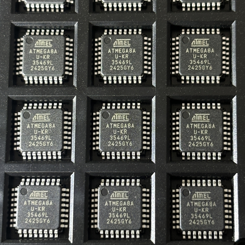
The AUR version uses a 32-lead TQFP package. This package provides eight ADC channels and fits compact surface-mount PCB designs.
The most useful way to understand ATMEGA8A-AUR is to separate the device specification from the logistics code: ATmega8A describes the microcontroller, AU identifies the TQFP package option, and the final R indicates Tape & Reel supply for automated manufacturing.
ATMEGA8A-AUR Key Specifications
| Feature | ATMEGA8A-AUR | Engineering Meaning |
|---|---|---|
| Architecture | 8-bit AVR RISC | Simple embedded control architecture |
| Maximum Frequency | Up to 16 MHz | Enough speed for many control and monitoring tasks |
| Flash Memory | 8 KB | Stores firmware and application code |
| SRAM | 1 KB | Stores temporary runtime data |
| EEPROM | 512 Bytes | Stores persistent settings and calibration information |
| Programmable I/O | 23 Lines | Supports sensors, controls, switches, LEDs, and interfaces |
| ADC | 8-channel, 10-bit | Available in the TQFP package |
| PWM | 3 Channels | Useful for LED, motor, fan, and actuator control |
| Serial Interfaces | USART, SPI, TWI | Connects external modules and ICs |
| Operating Voltage | 2.7 V to 5.5 V | Fits many standard embedded supply rails |
| Package | 32-lead TQFP | Compact surface-mount format |
| Packaging | Tape & Reel | Optimized for automated SMT production |
Specifications become more useful when they are translated into real design decisions. An 8 KB program memory, for example, may be more than enough for a sensor reader, timer controller, relay board, alarm circuit, small user interface, or compact machine-control module.
However, engineers should not judge program memory only by the first prototype. Production firmware often gains diagnostics, configuration functions, error handling, safety routines, communication commands, factory test features, and calibration code.
The ATMEGA8A-AUR works best when those final firmware requirements can still fit comfortably inside the device's available resources.
ATMEGA8A-AUR vs ATMEGA8A-AU: What Is the Difference?
This is one of the most important questions for engineers and purchasing teams searching for the ATMEGA8A-AUR.
| Item | ATMEGA8A-AUR | ATMEGA8A-AU |
|---|---|---|
| MCU Family | ATmega8A | ATmega8A |
| CPU | 8-bit AVR | 8-bit AVR |
| Flash | 8 KB | 8 KB |
| SRAM | 1 KB | 1 KB |
| EEPROM | 512 Bytes | 512 Bytes |
| Package | 32-lead TQFP | 32-lead TQFP |
| Pinout | Same | Same |
| PCB Footprint | Same | Same |
| Main Difference | Tape & Reel | Non-Reel Ordering Option |
| Typical Use | Automated SMT production | Prototype or alternative production packaging |
From an electrical design point of view, engineers do not normally need a different schematic or PCB footprint when changing between ATMEGA8A-AU and ATMEGA8A-AUR.
The distinction becomes important during procurement and manufacturing. Tape-and-reel components can be loaded directly into compatible SMT placement equipment. This makes the AUR option particularly suitable for higher-volume PCBA assembly.
For a manual prototype, sample board, or small engineering quantity, packaging may have little effect on circuit behavior. For a production line building thousands of boards, packaging format becomes a real manufacturing requirement.
ATMEGA8A-AUR is not a faster or larger-memory version of ATMEGA8A-AU. The R mainly changes how the same TQFP device is supplied to the assembly process.
Why Tape & Reel Matters in Real Production
Packaging is sometimes ignored during early component selection because engineers naturally focus on voltage, frequency, memory, pinout, and peripheral features. Once a project reaches mass production, packaging can become just as important.
Automated PCB assembly equipment normally uses component feeders. A reel containing correctly oriented parts allows the pick-and-place machine to remove each IC, position it accurately, and mount it on the PCB at high speed.
This workflow reduces manual handling and supports consistent production.
For this reason, an engineering BOM should identify the exact ordering code rather than simply listing "ATmega8A." If the manufacturing line expects a tape-and-reel component, specifying ATMEGA8A-AUR can prevent confusion between electrically compatible but differently packaged stock.
This is an example of an important engineering lesson: component selection does not end with the circuit diagram. Manufacturing format, storage, traceability, assembly method, and supply-chain availability are part of the design.
ATMEGA8A-AUR Integrated Circuit Design Considerations
A successful integrated circuit design must consider the entire environment around the MCU. The ATMEGA8A-AUR may be the decision-making center of a board, but power stability, signal integrity, grounding, protection, and PCB layout determine whether the finished product behaves reliably.
Decoupling capacitors should be placed close to the relevant supply pins. This helps provide short bursts of current and reduces local supply noise.
Analog and digital routing also deserve attention. When the ADC is used to measure low-level sensor signals, designers should avoid routing high-current switching paths or noisy digital signals directly beside sensitive analog traces.
The AVCC and AREF connections are particularly important when ADC accuracy matters. A clean reference and sensible grounding can often improve measurement performance more than complicated software filtering.
The reset circuit should also be designed for the real supply environment. Brown-out detection can help protect against unpredictable behavior if the power rail falls below a suitable operating level.
Clock selection depends on application requirements. The internal calibrated oscillator may be suitable for many control tasks, while designs that need tighter timing accuracy can use an external clock source or crystal arrangement.
ATMEGA8A-AUR in an Integrated Circuit Card
An integrated circuit card or embedded controller board normally combines several functional sections around the MCU.
A typical board might include voltage regulation, the ATMEGA8A-AUR, communication transceivers, sensors, connectors, status LEDs, push buttons, MOSFET output drivers, EEPROM devices, and protection components.
The microcontroller can coordinate these blocks through its programmable I/O and serial interfaces. Digital outputs may control indicator LEDs, relays, transistor drivers, or enable signals. Digital inputs can monitor switches, limit sensors, fault outputs, or other logic signals.
Analog inputs can monitor voltage, temperature, light, current, pressure, or other sensor signals.
Because the ATMEGA8A-AUR provides 23 programmable I/O lines, engineers should map pins carefully before the PCB is finalized. A design that uses nearly every available pin has less room for debugging, production testing, future functions, or product variants.
PMIC Power Management Integrated Circuit and ATMEGA8A-AUR
The MCU is only one part of the power architecture. A product may also use a regulator, DC-DC converter, supervisor, charger, protection controller, or a more advanced PMIC power management integrated circuit.
These components do not replace the ATMEGA8A-AUR. Instead, they handle different responsibilities.
The MCU processes data and makes logical decisions. The power-management section provides suitable voltages, monitors supply conditions, switches loads, manages battery charging, or protects the system.
For example, a battery-powered monitoring device could use a power IC to produce a stable 3.3 V or 5 V rail. ATMEGA8A-AUR could then sample sensors, monitor user inputs, update LEDs, and communicate with another module.
In an industrial board powered from a higher input voltage, a DC-DC converter may reduce the incoming voltage before a regulator supplies the MCU.
Good embedded design separates power-management responsibilities from processing responsibilities. Reliable firmware cannot compensate for an unstable power rail.
ADC and Analog Sensor Applications
The 32-TQFP ATMEGA8A-AUR provides an 8-channel 10-bit ADC. This makes the device useful for embedded systems that need to measure several analog signals.
Common examples include thermistors, potentiometers, battery voltage dividers, current-sense circuits, pressure sensors, analog temperature sensors, light sensors, and other transducers.
A light-dependent resistor provides a simple example. An LDR can be combined with a fixed resistor to form a voltage divider. The ADC measures the divider output, allowing firmware to estimate changes in light level.
People searching terms such as ldr price philippines electronic components may be evaluating low-cost sensors and related components for educational projects, prototypes, repair work, or production.
Price is useful, but designers should also check resistance range, sensitivity, tolerance, temperature behavior, physical dimensions, and long-term availability.
For accurate ADC performance, engineers should also evaluate reference voltage quality, PCB noise, sensor impedance, sampling speed, grounding, filtering, and calibration.
USART, SPI, and Two-Wire Communication
ATMEGA8A-AUR supports several commonly used embedded communication methods. These interfaces make it possible to build systems that exchange information with sensors, memories, communication devices, displays, and other controllers.
USART
The programmable USART is useful for serial terminals, debugging connections, communication modules, industrial interfaces, and communication with another microcontroller.
SPI
SPI supports master and slave operation and can connect displays, memories, ADCs, DACs, sensors, and other digital integrated circuits.
TWI
The byte-oriented two-wire interface can connect compatible sensors, RTC devices, EEPROMs, expanders, and other peripherals using a compact shared bus.
The right communication method depends on speed, wiring, electrical environment, number of peripherals, software requirements, and available pins.
SPI often provides fast transfers but needs more signals. Two-wire communication is convenient when several addressed devices share the same lines. USART is widely used for straightforward serial data exchange.
Timers, PWM, and Real-Time Embedded Control
ATMEGA8A-AUR includes two 8-bit timer/counters and one 16-bit timer/counter. These hardware blocks allow the MCU to perform timing operations without relying entirely on software delays.
Timers can be used for periodic sensor sampling, pulse measurement, event scheduling, frequency generation, input capture, and timeout detection.
Three PWM channels are available. PWM is commonly used for LED brightness, fan control, motor command signals, heater control, simple audio generation, and other variable-duty-cycle outputs.
The important design principle is that the MCU normally provides the control signal rather than the full load current. A motor, relay, heater, solenoid, or high-power LED should usually be driven through an appropriate MOSFET, transistor, relay driver, motor driver, or power-control IC.
Connecting high-current loads directly to MCU pins can damage the device or create unstable behavior.
Power Consumption and Sleep Modes
Low-power design is not only about selecting a low-current MCU. Firmware behavior, clock speed, peripheral usage, regulator efficiency, pull-up resistors, sensors, displays, and external circuits all contribute to total system power.
ATmega8A provides several sleep modes, including Idle, ADC Noise Reduction, Power-save, Power-down, and Standby.
These modes allow firmware to stop or reduce activity in parts of the device when full processing performance is not needed.
A battery-powered sensor might wake periodically, measure an input, store or transmit the result, and then return to a low-power state.
This duty-cycled approach can reduce average current consumption significantly compared with running every peripheral continuously.
However, power optimization should be measured at the complete board level. A sleeping MCU cannot create a low-power product if another component consumes substantial current all the time.
Firmware Design Strategy for ATMEGA8A-AUR
The 8 KB Flash and 1 KB SRAM encourage disciplined firmware design. That can actually be an advantage because engineers are pushed to understand memory use and execution behavior clearly.
A practical firmware architecture can separate GPIO functions, ADC routines, timer control, communication drivers, EEPROM management, error handling, and application logic.
This makes the firmware easier to test and maintain.
SRAM requires particular attention. Large arrays, oversized serial buffers, unnecessary global variables, deep function nesting, and uncontrolled dynamic allocation can consume 1 KB quickly.
Interrupt service routines should also remain short. An interrupt can record an event, capture a value, or move incoming data into a small buffer. More complex processing can then occur in the main application.
Long blocking delays should be avoided when the MCU needs to perform several jobs at once. Timer-driven state machines are often a cleaner solution for reading sensors, checking buttons, updating outputs, and handling serial communication.
Reliable PCB Design for ATMEGA8A-AUR
A good MCU cannot compensate for every PCB problem. Careful layout and protection are necessary if the product is expected to operate reliably outside a laboratory.
- Place bypass capacitors close to MCU supply pins.
- Keep analog traces away from noisy switching currents.
- Route AVCC and AREF carefully.
- Provide reliable reset and brown-out behavior.
- Keep ISP programming signals accessible.
- Add useful production test points.
- Use suitable drivers for high-current loads.
- Protect external connectors against ESD where required.
- Verify the exact 32-TQFP footprint before PCB fabrication.
- Review ground and return-current paths before release.
External connections deserve special attention. A cable leaving the board can bring electrical noise, electrostatic discharge, unexpected voltage, and ground differences into the circuit.
Appropriate filtering, transient protection, level translation, isolation, or dedicated communication transceivers should be added according to the installation environment.
ATMEGA8A-AUR for Industrial Control
ATMEGA8A-AUR can be used in industrial and commercial systems where a small MCU must monitor inputs and control outputs predictably.
Potential applications include counters, control panels, sensor interfaces, small machine controllers, environmental monitors, alarm modules, lighting controls, test equipment, digital instruments, and replacement control boards.
Industrial systems often operate near motors, contactors, long cables, switching power supplies, and other sources of electrical noise.
The MCU should therefore be supported by appropriate protection and interface circuits.
For example, an industrial 24 V input should not connect directly to a logic-level ATMEGA8A-AUR pin. The signal should first pass through a suitable interface that provides voltage translation and protection.
Likewise, long-distance communication should use an appropriate physical-layer transceiver rather than sending raw MCU logic levels through a long cable.
ATMEGA8A-AUR vs ATMEGA16A-AU: When More Memory Helps
Engineers evaluating an ATmega8A design may also consider a larger AVR device such as ATMEGA16A-AU.
| Feature | ATMEGA8A-AUR | ATMEGA16A-AU |
|---|---|---|
| Architecture | 8-bit AVR | 8-bit AVR |
| Maximum Frequency | 16 MHz | 16 MHz |
| Flash | 8 KB | 16 KB |
| SRAM | 1 KB | 1 KB |
| EEPROM | 512 Bytes | 512 Bytes |
| Programmable I/O | 23 | 32 |
| Typical Position | Compact control design | Larger I/O and firmware design |
ATMEGA8A-AUR makes sense when 8 KB Flash and 23 I/O lines provide enough margin for the complete product.
ATMEGA16A-AU becomes more attractive when firmware is expected to grow or the board requires significantly more I/O.
This is not simply a question of selecting the device with larger numbers. Using a larger MCU can increase cost or board requirements. Using a device that is too small can create redesign work.
A good MCU choice leaves enough engineering margin for the final product without paying for large amounts of capability the application will never use.
Is ATMEGA8A-AUR Good for New Designs?
ATMEGA8A-AUR can still be a practical choice when the application matches its capabilities.
It is especially useful when a project needs simple digital control, analog measurement, timers, PWM, non-volatile configuration storage, and common serial interfaces.
It can also make sense for maintaining established AVR platforms, replacement boards, industrial equipment, educational products, or systems where a company already has working firmware and engineering experience with the AVR architecture.
A newer processor may be more appropriate if the product requires Wi-Fi, Bluetooth, complex USB functions, large graphical interfaces, extensive RAM, advanced security, digital signal processing, or operating-system support.
The correct decision should therefore be based on application requirements rather than processor age.
A Deeper View of MCU Performance
Microcontroller performance is often reduced to clock frequency, but embedded systems should be evaluated differently.
Suppose a controller needs to read a temperature sensor every 200 milliseconds, update a relay, process several buttons, store a setting, and respond to serial commands.
If ATMEGA8A-AUR completes all of those operations within the required timing limits, a processor running ten or twenty times faster may provide no meaningful benefit to the customer.
The more important questions are whether the MCU can meet worst-case timing, whether memory is sufficient, whether the interfaces match the circuit, and whether the complete system remains reliable.
This is why mature 8-bit devices continue to appear in practical equipment. Simple architecture, predictable startup, understandable peripheral behavior, low firmware complexity, and established programming tools can be valuable engineering advantages.
Common ATMEGA8A-AUR Applications
- Industrial control modules
- Temperature controllers
- Sensor monitoring systems
- Digital measuring equipment
- LED lighting controllers
- Fan speed controllers
- Motor control interfaces
- Relay control boards
- Alarm systems
- Battery monitoring products
- Environmental sensors
- Educational AVR boards
- Integrated circuit cards
- Small automation systems
- Protocol interface boards
- Access control equipment
- Machine monitoring modules
- Replacement controller boards
The common theme is straightforward embedded control. These products need a processor that connects efficiently to real hardware without requiring a large software platform.
Electronic Components Store Near Me: Buying ATMEGA8A-AUR Locally
A search such as electronic components store near me often comes from an engineer who needs components quickly for a prototype, repair, or test.
Local stores are convenient for resistors, capacitors, connectors, sensors, development boards, and common integrated circuits.
ATMEGA8A-AUR is more specific because the full ordering code includes the Tape & Reel requirement. Many local stores focus on small quantities and may stock ATMEGA8A-AU rather than full reels of ATMEGA8A-AUR.
If the electrical design only needs a few prototype devices, the AU version may be suitable if all other specifications match. For an automated production line, the purchasing team should confirm whether AUR packaging is required.
Unrelated technical searches such as determine the x component of the force on the electron may also appear around electronics education content. That phrase is a physics calculation, not a semiconductor ordering specification. For component sourcing, exact manufacturer part numbers provide much better results.
Electronic Components Online and ATMEGA8A-AUR Sourcing
Searching for electronic components online gives engineers access to a much larger range of semiconductor inventory than most physical stores can offer.
Queries for electronic parts online can be filtered by manufacturer, part number, package, quantity, lifecycle status, stock level, and technical parameters.
Purchasing professionals may also use search phrases such as master electronics online components when comparing distributor channels and component availability.
For ATMEGA8A-AUR, purchasing teams should check more than the visible stock number. They should confirm that the exact AUR ordering code is being supplied, especially when the manufacturing line requires Tape & Reel.
They should also evaluate documentation, traceability, storage history, packaging condition, lead time, supplier reputation, and the quantity required for the production schedule.
Where to Buy Electronic Components for Production
People asking where to buy electronic components usually have several options: authorized distributors, specialist distributors, independent suppliers, local electronics stores, manufacturer channels, and online marketplaces.
The right source depends on the project.
A prototype engineer may prioritize fast shipping and the ability to buy five pieces. A production buyer may care more about reels, factory traceability, date codes, storage conditions, inspection, long-term supply, and consistent lot quality.
For ATMEGA8A-AUR, use the full manufacturer ordering code instead of searching only for "ATmega8."
- Confirm the complete ATMEGA8A-AUR ordering code.
- Verify 32-lead TQFP packaging.
- Confirm Tape & Reel supply.
- Check required quantity and reel format.
- Verify operating range requirements.
- Review available traceability.
- Check moisture and storage handling.
- Compare lead time and total procurement risk.
- Confirm current manufacturer documentation.
- Inspect supplier reputation for production orders.
The cheapest unit price does not always produce the lowest manufacturing cost. Incorrect packaging, questionable traceability, damaged leads, moisture problems, or inconsistent devices can create rework and production delays that cost much more than the original component saving.
Why Exact Ordering Codes Matter in a BOM
One of the clearest lessons from ATMEGA8A-AUR is that every character in a part number can matter.
An engineer might casually write "ATmega8A" in a discussion. That may be enough when talking about software architecture. It is not always enough for a production BOM.
A manufacturing BOM should identify the actual ordering option required by the assembly process.
ATMEGA8A-AUR tells the procurement team that the design is using the ATmega8A device in the AU TQFP package with Tape & Reel supply.
This reduces ambiguity between engineering, procurement, warehousing, quality control, and contract manufacturing teams.
A precise BOM is one of the simplest ways to reduce avoidable supply-chain mistakes.
Frequently Asked Questions About ATMEGA8A-AUR
What is ATMEGA8A-AUR?
ATMEGA8A-AUR is a Tape & Reel ordering option for the ATmega8A 8-bit AVR microcontroller in a 32-lead TQFP package. It provides 8 KB Flash, 1 KB SRAM, 512 bytes EEPROM, timers, PWM, ADC, USART, SPI, TWI, and programmable I/O.
Is ATMEGA8A-AUR the same as ATMEGA8A-AU?
They use the same ATmega8A microcontroller and the same 32-lead TQFP package. The important ordering difference is that ATMEGA8A-AUR is supplied in Tape & Reel packaging.
What does the R in ATMEGA8A-AUR mean?
The final R identifies the Tape & Reel ordering option. This packaging format is commonly used for automated SMT assembly.
Does ATMEGA8A-AUR have 8 KB Flash?
Yes. ATmega8A provides 8 KB of in-system programmable Flash program memory, 1 KB SRAM, and 512 bytes EEPROM.
What package does ATMEGA8A-AUR use?
ATMEGA8A-AUR uses a 32-lead TQFP package.
How many ADC channels does ATMEGA8A-AUR have?
The TQFP version provides eight 10-bit ADC channels.
How many programmable I/O pins does ATmega8A have?
ATmega8A provides 23 programmable I/O lines.
What is the maximum operating frequency?
ATmega8A supports operation up to 16 MHz when used within the required electrical conditions.
Can ATMEGA8A-AUR control motors?
Yes, it can generate logic and PWM control signals, but motor current should normally be handled by an appropriate motor driver, MOSFET, transistor stage, or other power interface.
Where can I buy ATMEGA8A-AUR?
Search using the complete ATMEGA8A-AUR manufacturer ordering code and compare reputable electronic component suppliers based on stock, Tape & Reel packaging, traceability, lead time, documentation, and production requirements.
Final Thoughts on ATMEGA8A-AUR
The ATMEGA8A-AUR is a useful example of how a mature microcontroller can continue to solve practical embedded problems without requiring unnecessary complexity.
Its 8 KB Flash, 1 KB SRAM, 512-byte EEPROM, 23 programmable I/O lines, eight-channel ADC in the TQFP package, timers, three PWM channels, USART, SPI, and two-wire interface create a balanced platform for many small control systems.
The AUR ordering code also carries an important manufacturing detail. It identifies the Tape & Reel supply option for the 32-lead TQFP device, making it particularly relevant for automated SMT assembly.
The difference between ATMEGA8A-AUR and ATMEGA8A-AU is a good reminder that production engineering is not only about electrical specifications. Packaging, logistics, traceability, and assembly requirements are part of component selection too.
For compact sensor systems, industrial interfaces, monitoring modules, lighting products, alarm equipment, motor-control interfaces, educational boards, and established AVR platforms, ATMEGA8A-AUR can still provide a practical combination of control capability and implementation simplicity.
The final choice should always consider firmware size, I/O requirements, ADC needs, power architecture, PCB space, sourcing strategy, manufacturing method, expected product lifetime, and future development.
A successful design is not created by selecting the MCU with the highest clock rate or the largest memory. It comes from choosing a component whose capabilities match the real application while leaving enough margin for reliable production and long-term support.