

STTH6110TV2 1000V Ultrafast Recovery Diode: Specs, Design & Applications
A practical engineering guide to STTH6110TV2 specifications, 1000 V high-voltage operation, dual ultrafast recovery behavior, ISOTOP packaging, switching losses, thermal design, industrial applications, replacement selection, and component sourcing.
What Is STTH6110TV2?
STTH6110TV2 is a high-voltage dual ultrafast recovery rectifier from STMicroelectronics. It is designed for applications that need fast switching, high reverse-voltage capability, significant current handling, and an electrically insulated power package. The device is rated for 1000 V repetitive peak reverse voltage and 2 × 30 A average forward current, with a typical reverse recovery time of about 42 ns under the datasheet test conditions.
The STTH6110TV2 is not simply a high-current diode with a large voltage number. Its real value becomes clear when a designer looks at the complete switching system: reverse recovery, conduction loss, thermal resistance, isolation, current pulses, PCB or busbar layout, heat-sink design, and the behavior of the switching transistor connected around the diode.
In industrial power electronics, diode selection can affect efficiency, temperature, electromagnetic noise, transistor stress, and long-term reliability at the same time. A slower rectifier may still conduct current correctly in a static test, but during switching it can create significant reverse-recovery current. That current adds switching loss and can increase voltage and current stress elsewhere in the converter.
STTH6110TV2 addresses this class of problem with ultrafast, soft-recovery behavior, high reverse-voltage capability, and an insulated ISOTOP package intended for demanding high-power applications.

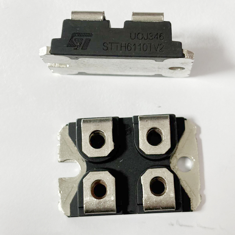
SEO image note: descriptive ALT text is intentionally used to connect the visual with STTH6110TV2, ultrafast recovery diodes, industrial power supplies and power-conversion design without falsely identifying the pictured hardware as the exact STTH6110TV2 device.
STTH6110TV2 Key Specifications
The easiest way to understand the STTH6110TV2 is to translate its electrical specifications into real engineering meaning. A specification such as 1000 V reverse voltage is not only a number for a product filter. It defines the maximum repetitive reverse-voltage class the diode is designed to withstand and therefore influences where it can safely sit inside a high-voltage converter.
| Parameter | STTH6110TV2 | Design Meaning |
|---|---|---|
| Manufacturer | STMicroelectronics | ST high-voltage ultrafast rectifier family |
| Device Type | Dual Ultrafast Recovery Diode | Designed for high-speed power switching |
| Reverse Voltage | 1000 V | High-voltage converter and industrial power use |
| Average Forward Current | 2 × 30 A | Two high-current diode elements |
| RMS Forward Current | 60 A per diode rating condition | Important for current waveform analysis |
| Typical Forward Voltage | Approx. 1.3 V | Influences conduction loss |
| Typical Reverse Recovery Time | 42 ns | Supports high-frequency switching |
| Non-Repetitive Surge Current | 240 A | Useful when evaluating short transient stress |
| Maximum Junction Temperature | 150°C | Defines thermal operating boundary |
| Package | ISOTOP | Large insulated power package |
| Package Isolation | 2500 VRMS | Helps simplify insulated heat-sink mounting |
| Delivery Format | Tube | Relevant to procurement and assembly planning |
The important point is that these values should not be treated independently. Current capacity depends strongly on junction temperature, case temperature, cooling, waveform, duty cycle, switching conditions, and mounting quality.
A 30 A current rating does not mean that every design can simply pass 30 A through the diode without thermal analysis. Power semiconductor ratings always need to be interpreted together with temperature and cooling conditions.
Why Ultrafast Reverse Recovery Matters
A conventional diode looks simple: it conducts in one direction and blocks voltage in the other. In a switching converter, the transition between these two states becomes much more important.
When a diode has been conducting forward current and is suddenly reverse biased, stored charge inside the device must be removed before the diode fully blocks reverse voltage. During this short interval, current can flow in the reverse direction.
This behavior is described by reverse recovery.
The STTH6110TV2 ultrafast recovery diode is designed to reduce the time and energy associated with this transition compared with slower conventional rectifiers.
That can matter greatly in high-frequency power conversion because reverse-recovery current often passes through the switching transistor. The transistor must handle not only the intended load current but also the temporary recovery current of the diode.
Why 42 ns Should Not Be Used as a Universal Number
The often-quoted 42 ns typical reverse recovery time is measured under defined test conditions. Real reverse recovery changes with forward current, junction temperature, reverse voltage, and the rate at which current is forced to change.
Therefore, engineers should not calculate an entire converter only from one headline recovery-time value. The recovery curves and test conditions in the STTH6110TV2 datasheet are more useful when performing detailed switching analysis.
The deeper design question is not simply "How many nanoseconds is the diode?" It is "How much recovery current and recovery charge will the complete switching stage experience under its real operating conditions?"
Soft Recovery and EMI Behavior
Recovery speed is only part of diode behavior. The shape of the recovery current also matters.
A diode that stops conducting extremely abruptly can create a large current slope. Combined with parasitic inductance in the package, wiring, transformer, busbar, and PCB, this can produce voltage overshoot and ringing.
The STTH6110TV2 is described as having ultrafast, soft recovery. Soft recovery aims to make the transition more controlled instead of ending with an extremely sharp current change.
This can help reduce the severity of switching noise in some converter designs. It does not remove the need for good layout or snubber design, but it can make the diode easier to integrate into high-power switching stages.
Designers should still keep high-di/dt current loops short, use suitable bus structures, minimize stray inductance, and measure real switching waveforms during prototype validation.
STTH6110TV2 Conduction and Switching Losses
Diode power loss can be divided into two broad categories: conduction loss and switching loss.
Conduction Loss
When the STTH6110TV2 conducts forward current, a voltage appears across the diode. Multiplying this voltage by current gives an approximate view of instantaneous conduction power.
However, real converter waveforms are rarely constant DC. Current may be triangular, sinusoidal, pulsed, discontinuous, or strongly affected by transformer and inductor behavior.
For this reason, an engineer should consider average current, RMS current, duty cycle, forward-voltage characteristics, and junction temperature when estimating loss.
Switching Loss
During commutation, reverse recovery generates additional energy loss. At low switching frequency this contribution may be modest. At higher switching frequency, recovery energy repeated tens of thousands of times per second can become significant.
This is one reason a fast recovery rectifier such as STTH6110TV2 is useful in converters where a standard low-frequency rectifier would create excessive switching loss.
Selecting a diode with a slightly lower forward voltage is not always the lowest-loss solution. In a high-frequency converter, a device with better recovery behavior may reduce total system loss even if its static forward-voltage number looks similar.
Why the STTH6110TV2 ISOTOP Package Matters
The ISOTOP package is a major part of the STTH6110TV2 design. It is not simply a large case around the semiconductor.
High-power diode modules must transfer heat efficiently from the silicon to the cooling system while also handling high electrical voltage. Mechanical mounting, electrical isolation, thermal resistance, creepage, clearance, and terminal connection all become part of the power design.
ST specifies an insulated ISOTOP package with electrical insulation rated at 2500 VRMS. This gives designers an integrated isolation barrier between the power semiconductor structure and the mounting surface.
Heat-Sink Integration
The large module format allows the diode to be mounted to a suitable cooling surface, making thermal management more practical in high-power equipment.
Insulated Package
Electrical isolation between the device and mounting surface can simplify mechanical design compared with solutions requiring separate insulation hardware.
Low-Inductance Connections
Short, wide external connections can help control parasitic inductance and improve switching behavior in high-current circuits.
Thermal interface material and mounting pressure remain important. Even a well-designed insulated package can run hot if the contact surface is uneven, thermal compound is poorly applied, the heat sink is undersized, or airflow is inadequate.

Thermal Design for STTH6110TV2
Thermal design should begin before the final PCB and mechanical enclosure are finished.
The STTH6110TV2 has a maximum junction temperature of 150°C. That number is an absolute operating boundary, not a recommended normal design target.
Long-term reliability usually benefits from maintaining useful thermal margin. The exact margin depends on mission profile, ambient temperature, load cycle, cooling method, expected equipment life, and reliability requirements.
The datasheet lists junction-to-case thermal resistance values for the diode elements and also describes thermal coupling when both diode elements operate.
This becomes important because both semiconductor elements share the same power module. Heat generated by one diode can influence the thermal environment of the other.
A Practical Thermal Workflow
- Estimate conduction loss from the real current waveform.
- Estimate reverse-recovery and switching losses.
- Calculate expected case and junction temperatures.
- Include thermal interaction when both diodes operate.
- Select an appropriate heat sink and interface material.
- Check airflow under worst-case ambient conditions.
- Measure case temperature during prototype testing.
- Validate junction-temperature margin at maximum load.
Thermal testing should be performed with realistic electrical switching conditions because static current tests may not include recovery loss, transistor interaction, magnetic heating, or enclosure temperature rise.
1000 V Reverse Voltage: How Much Margin Is Enough?
STTH6110TV2 belongs to the 1000 V ultrafast diode class. That makes it attractive for high-voltage DC buses and converter stages where lower-voltage rectifiers do not provide enough blocking capability.
However, a 1000 V diode should not automatically be placed across a circuit that repeatedly produces nearly 1000 V during normal operation.
Real circuits contain leakage inductance, wiring inductance, transformer parasitics, switching delays, control transients, and grid disturbances. These can produce short voltage spikes above the expected steady-state value.
Good engineering therefore includes voltage margin and waveform measurement.
Designers should evaluate the highest expected DC bus, transformer ratio, regenerative conditions, startup behavior, abnormal load conditions, and switching overshoot before selecting the voltage class.
Snubbers, clamps, TVS devices, active clamping, and improved layout may be used when necessary to control transient voltage.
Surge Current and Pulsed Operation
The STTH6110TV2 datasheet specifies a non-repetitive surge forward current of 240 A under defined conditions. The device also supports high pulsed-current operation.
This does not mean the diode can continuously carry hundreds of amps.
Surge current ratings describe short-duration events. Examples may include capacitor charging, startup transients, fault clearing, or temporary overload conditions.
The semiconductor junction has thermal mass, so it can tolerate a short pulse that would be impossible to sustain continuously.
For repeated pulsed operation, designers must examine pulse width, repetition rate, initial junction temperature, thermal impedance, and cooling.
Peak current, average current, and RMS current describe different stresses. A reliable design should never replace one of these values with another simply because all of them use amperes.
STTH6110TV2 Applications
STMicroelectronics positions the STTH6110TV family for demanding power applications including industrial power supplies, motor control, rectification, freewheeling, snubber functions, bootstrap circuits, and demagnetization.
- Industrial AC/DC power supplies
- High-voltage DC/DC converters
- Motor drive power stages
- Inverter freewheeling paths
- Power factor correction systems
- Welding power supplies
- Battery charging equipment
- Industrial UPS systems
- Snubber networks
- Bootstrap circuits
- Transformer demagnetization circuits
- High-frequency rectification
- Energy conversion equipment
- Industrial automation power modules
The device is especially relevant where switching speed and voltage capability are both important. A 1000 V rectifier that is fast enough for high-frequency operation can support power topologies where a conventional mains-frequency diode would be unsuitable.
STTH6110TV2 in Industrial Power Supplies
Industrial power supplies are one of the most natural application areas for STTH6110TV2.
Large power supplies can contain several conversion stages. The input may first be rectified and filtered, followed by power factor correction, high-frequency switching, transformer isolation, secondary rectification, and output regulation.
Depending on topology and location, an ultrafast diode may be used for high-voltage rectification, freewheeling, clamping, reset paths, or auxiliary power functions.
Industrial equipment often operates continuously and may experience elevated ambient temperature, dust, vibration, grid disturbances, repeated load changes, and long service intervals.
In these applications, ruggedness and predictable thermal behavior may be more important than saving a small amount of component cost.
STTH6110TV2 in Motor Control and Inverters
Motor-control converters contain rapidly switching current paths. Inductive motor currents cannot change instantly, so current requires a controlled path when a transistor changes state.
Freewheeling diodes can provide this path.
A poor diode choice may increase switching losses, voltage overshoot, EMI, and transistor stress. An ultrafast recovery device can therefore be useful in appropriate inverter and motor-drive architectures.
The exact choice depends on bus voltage, switching frequency, motor current, transistor technology, dead time, modulation method, cooling, and topology.
Designers should also consider whether the body diode of a MOSFET, an external ultrafast diode, a SiC diode, or another rectifier technology gives the best total system behavior.
STTH6110TV2 should therefore be selected at the converter level rather than simply as an isolated component.
Snubber, Bootstrap, and Demagnetization Functions
Not every high-power diode is used as the main output rectifier.
STTH6110TV2 can also be considered for auxiliary high-energy paths where fast switching and high voltage are important.
Snubber Circuits
A snubber controls voltage or current transients caused by switching and parasitic energy. A fast diode can direct this energy into a capacitor, resistor, clamp, or recovery path.
Bootstrap Functions
Some high-side gate-driver circuits use a diode to charge a bootstrap capacitor. In high-voltage systems, voltage rating and recovery characteristics can become important depending on switching frequency and topology.
Demagnetization
Magnetic components store energy. A demagnetization or reset path allows that energy to be controlled when a switching interval ends.
The required diode must tolerate the resulting current and reverse voltage while switching fast enough for the converter.
STTH6110TV2 vs Standard Recovery Rectifiers
| Design Factor | STTH6110TV2 Ultrafast Diode | Conventional Slow Rectifier |
|---|---|---|
| Primary Design Area | High-frequency power conversion | Low-frequency rectification |
| Reverse Recovery | Optimized for fast recovery | Usually much slower |
| Switching Loss | Designed to reduce recovery-related loss | Can become significant at high frequency |
| EMI Behavior | Soft-recovery design | Depends strongly on diode technology |
| Voltage Class | 1000 V | Varies by product |
| Package | Insulated ISOTOP module | Many package options |
A standard rectifier may be completely acceptable in a 50 Hz or 60 Hz bridge where switching speed is not important. The same diode can become inefficient in a converter operating at tens of kilohertz.
This is why diode technology should match the circuit frequency rather than being selected only from voltage and current ratings.
STTH6110TV2 vs SiC Diodes
Engineers looking for a STTH6110TV2 replacement may encounter silicon-carbide Schottky diodes.
SiC devices can offer extremely low reverse-recovery charge and strong high-temperature switching performance, which can be valuable in high-frequency converters.
However, replacing a silicon ultrafast diode with SiC is not automatically a drop-in optimization.
Cost, package, voltage rating, current capability, forward voltage, capacitance, surge behavior, topology, switching transistor, EMI behavior, heat-sink design, and mechanical mounting all need to be considered.
In some converters, STTH6110TV2 can provide an effective balance between recovery behavior, ruggedness, package isolation, current capability, and system cost.
A better semiconductor does not automatically create a better converter. Power-stage components must be optimized as a system because changing one device can alter switching speed, ringing, EMI, thermal distribution, and control behavior.
How to Select STTH6110TV2 for a New Design
A useful selection process starts with circuit requirements rather than the part number.
- Calculate maximum repetitive reverse voltage.
- Include switching overshoot and transient margin.
- Determine average diode current.
- Calculate RMS and peak current.
- Review reverse-recovery behavior at real temperature.
- Estimate conduction and switching losses.
- Calculate junction temperature at worst-case load.
- Confirm the ISOTOP package fits mechanical constraints.
- Validate cooling and heat-sink performance.
- Check the exact internal diode configuration and terminal connections.
- Review surge requirements.
- Verify current product status and sourcing availability.
A designer should also consider the switching transistor. The optimum diode for an IGBT converter may not be identical to the optimum diode for a MOSFET converter because switching speed, dead time, current slope, and commutation behavior can differ.
PCB, Busbar, and Wiring Design Around STTH6110TV2
The large ISOTOP package does not eliminate layout problems.
Any current loop with high di/dt contains parasitic inductance. When current changes quickly, even a small amount of inductance can generate significant voltage.
The power path between STTH6110TV2, the switching transistor, DC-link capacitor, transformer, and other high-current components should therefore be kept short and mechanically direct.
Wide copper areas, laminated bus structures, short terminals, suitable film capacitors, and carefully positioned snubber components can help reduce loop inductance.
Control wiring should also be separated from noisy power-current loops. Gate-driver signals, analog current sensing, feedback circuits, and communication signals can be affected by fast switching if routing is careless.
The objective is not simply a neat PCB. The objective is a predictable current path.
Testing STTH6110TV2 in a Prototype
A finished power converter should be validated under realistic conditions before entering production.
A basic multimeter diode test can confirm that a device is not obviously open or shorted, but it cannot verify high-voltage blocking behavior, reverse recovery, surge capability, thermal performance, or switching loss.
Prototype testing should examine operating waveforms with appropriate high-voltage differential probes and current measurement equipment.
Useful measurements may include diode voltage, forward current, reverse-recovery current, switching-node overshoot, transistor current, heat-sink temperature, and diode case temperature.
Engineers should repeat tests across load range, input-voltage range, ambient temperature, and abnormal operating states.
Power electronics can store dangerous energy. High-voltage testing should only be performed with suitable equipment, protective procedures, discharge paths, and trained personnel.
How to Find an STTH6110TV2 Replacement or Equivalent
A search for STTH6110TV2 equivalent or STTH6110TV2 replacement should not be based only on "1000 V and 30 A."
Several parameters must match closely enough for the real application.
| Replacement Check | What to Verify | Why It Matters |
|---|---|---|
| Reverse Voltage | 1000 V class or suitable higher margin | Prevents blocking-voltage overstress |
| Forward Current | Equal or suitable current capability | Affects conduction and thermal load |
| Configuration | Exact diode arrangement | Prevents incorrect circuit connection |
| Package | Mechanical and electrical compatibility | Determines mounting and terminal fit |
| Reverse Recovery | trr, Qrr, IRM and softness | Changes transistor loss and EMI |
| Forward Voltage | Compare across operating current | Changes conduction loss |
| Thermal Resistance | Junction-to-case performance | Changes heat-sink requirement |
| Isolation | Package insulation rating | Can affect mechanical safety design |
| Surge Rating | Transient current capability | Important during faults and startup |
Even when two diode modules have similar headline specifications, their switching behavior can differ enough to change ringing, transistor temperature, efficiency, and EMI.
For this reason, a replacement should be validated electrically and thermally in the actual converter.
STTH6110TV1 vs STTH6110TV2
STMicroelectronics lists both STTH6110TV1 and STTH6110TV2 within the same STTH6110TV family. They share the main family ratings such as 1000 V reverse voltage, 2 × 30 A average current capability, ISOTOP packaging, and the same general ultrafast-recovery technology.
However, designers should not assume that the two ordering codes are automatically interchangeable.
The internal diode connection and external terminal arrangement must match the original circuit. Before changing from one version to another, compare the manufacturer schematic, pinout, package drawing, and BOM requirements.
In power modules, "same voltage, same current, same package" is not enough to prove interchangeability. Internal topology is just as important as the headline ratings.
STTH6110TV2 Datasheet: What Engineers Should Read First
When reviewing the STTH6110TV2 datasheet, many buyers look only at the first-page specifications. Engineers should go deeper.
The most useful sections normally include absolute maximum ratings, thermal resistance, forward-voltage curves, reverse-recovery data, recovery charge, temperature dependence, package dimensions, internal configuration, and ordering information.
Graphs are especially important because semiconductor behavior changes continuously with current and temperature.
A table may provide a maximum value at one test condition, while the graphs show how the same parameter behaves throughout a much wider operating range.
This information helps engineers estimate whether the diode will still perform well at high temperature and during real switching conditions.
Why Low Leakage Current Matters
Reverse leakage current is sometimes overlooked because it is much smaller than normal forward current.
At high voltage and high temperature, however, leakage becomes more relevant.
Leakage generates power inside the device while it is blocking voltage. Semiconductor leakage also tends to increase with junction temperature.
This can create a feedback effect: temperature increases leakage, leakage increases dissipation, and additional dissipation raises temperature further.
ST highlights low leakage current and improved thermal-runaway guard band as advantages of the STTH6110TV design.
In equipment designed for long operating life, this type of behavior can matter as much as peak efficiency measured during a short laboratory test.
Is STTH6110TV2 Still Suitable for New Designs?
STTH6110TV2 remains an active STMicroelectronics product and can still be relevant for industrial power designs that match its voltage, current, switching, package, and thermal characteristics.
Whether it is the best choice for a new converter depends on the system.
Newer silicon ultrafast diodes and silicon-carbide devices may offer different trade-offs in recovery charge, forward voltage, capacitance, operating temperature, package size, and cost.
However, modern technology should not be selected only because it is newer.
A mature diode module can remain attractive when the mechanical platform is already proven, the cooling system matches the package, the converter switching frequency is appropriate, and long-term production experience is valuable.
The best decision comes from comparing total converter efficiency, cost, EMI, thermal performance, reliability, supply risk, and redesign effort.
Buying STTH6110TV2 for Production
When purchasing STTH6110TV2 STMicroelectronics components, the complete manufacturer part number should be used rather than searching only for STTH6110 or a generic "1000V diode module."
Power semiconductor modules are used in equipment where a questionable component can cause expensive system-level failures. Supplier selection therefore deserves more attention than simply comparing the lowest visible price.
- Confirm the exact STTH6110TV2 ordering code.
- Verify STMicroelectronics as the manufacturer.
- Confirm the ISOTOP package.
- Check required quantity and tube packaging.
- Review current manufacturer product status.
- Request traceability where required.
- Inspect package and terminals before assembly.
- Review storage conditions.
- Compare date-code requirements.
- Validate supplier quality for production volumes.
Searches such as buy STTH6110TV2, STTH6110TV2 price, and STTH6110TV2 in stock usually represent commercial intent. For production buyers, price should be evaluated together with authenticity, traceability, stock condition, lead time, and long-term supply capability.
Why Exact Part Numbers Matter in the BOM
A production BOM should contain STTH6110TV2, not simply "1000 V fast diode."
The exact ordering code reduces ambiguity between engineering, purchasing, incoming inspection, warehousing, contract manufacturing, and repair teams.
This becomes particularly important when related parts in the same family have different internal configurations.
A strong BOM may also include manufacturer name, package, internal manufacturer number, approved alternates, supplier codes, drawing references, and substitution notes.
Accurate BOM data is one of the simplest ways to prevent expensive purchasing mistakes.
Frequently Asked Questions About STTH6110TV2
What is STTH6110TV2?
STTH6110TV2 is a 1000 V dual ultrafast recovery power diode from STMicroelectronics in an insulated ISOTOP package. It is intended for high-power rectification, freewheeling, snubber, bootstrap, demagnetization, motor-control, and industrial power applications.
Who manufactures STTH6110TV2?
STTH6110TV2 is manufactured by STMicroelectronics.
What is the voltage rating of STTH6110TV2?
The device has a repetitive peak reverse-voltage rating of 1000 V.
What is the current rating of STTH6110TV2?
The family datasheet specifies an average forward-current capability of 2 × 30 A under the stated case-temperature and duty-cycle conditions.
What is the typical reverse recovery time?
The datasheet lists a typical reverse recovery time of approximately 42 ns under its specified test conditions. Reverse recovery changes with current, temperature, reverse voltage, and current slew rate.
What package does STTH6110TV2 use?
STTH6110TV2 uses the insulated ISOTOP power package.
What is the maximum junction temperature?
The maximum operating junction temperature is 150°C. A practical design should normally maintain suitable thermal margin below the absolute maximum.
Can STTH6110TV2 be used for motor control?
Yes. STMicroelectronics identifies motor control and freewheeling among the relevant application areas for this diode family, provided the actual circuit voltage, current, switching frequency, and thermal conditions match the device requirements.
Is STTH6110TV2 a normal rectifier diode?
It is a rectifier, but it is specifically designed as a high-voltage ultrafast recovery device for switching applications rather than only low-frequency mains rectification.
Can I replace STTH6110TV2 with another 1000 V 30 A diode?
Not automatically. A replacement should also match internal configuration, package, pinout, reverse-recovery behavior, thermal resistance, forward voltage, surge capability, isolation, and switching requirements.
Is STTH6110TV2 an IC?
No. It belongs to discrete semiconductor products, specifically high-voltage ultrafast diodes and rectifiers.
What category should STTH6110TV2 be listed under?
A suitable product category is Discrete Semiconductors → Diodes & Rectifiers → Ultrafast Recovery Rectifiers or Fast Recovery Diode Modules.
Final Thoughts on STTH6110TV2
The STTH6110TV2 is best understood as a complete power-switching component rather than simply a "1000 V, 30 A diode."
Its combination of 1000 V reverse-voltage capability, two high-current diode elements, ultrafast soft recovery, high pulsed-current capability, insulated ISOTOP packaging, and industrial power orientation makes it suitable for demanding converter designs.
Its typical 42 ns reverse-recovery specification can be useful in high-frequency circuits, but designers should also study recovery current, recovery charge, temperature dependence, forward-voltage behavior, thermal resistance, and circuit parasitics.
The strongest power-electronics design does not select a diode only from voltage and current ratings. It treats the diode, switching transistor, magnetic components, DC-link capacitor, snubber, layout, cooling system, and control strategy as one interacting system.
For industrial power supplies, motor control, rectification, freewheeling, snubber circuits, bootstrap functions, and demagnetization paths, STTH6110TV2 remains a practical device when the application requirements match its electrical and thermal characteristics.
Engineers considering a STTH6110TV2 replacement should compare much more than nominal current and voltage. Package compatibility, internal configuration, recovery characteristics, surge current, thermal behavior, mechanical mounting, electrical isolation, and sourcing quality can all affect the success of a substitution.
For purchasing teams, the exact STTH6110TV2 manufacturer part number should be maintained throughout the BOM and supply chain. Correct identification helps avoid configuration errors and ensures that engineering, procurement, production, quality control, and maintenance teams are working with the same component definition.
Ultimately, STTH6110TV2 demonstrates an important principle in power semiconductor engineering: the right diode is not necessarily the device with the largest headline ratings. The right diode is the one whose switching behavior, thermal limits, package, voltage margin, current capability, and long-term reliability fit the complete converter.