

CH340G USB to Serial UART Converter: Pinout, Design & Applications
A practical engineering guide to the WCH CH340G USB-to-UART converter, covering pin functions, USB communication, UART signals, baud rates, 12 MHz crystal design, 3.3 V and 5 V systems, Arduino applications, PCB layout, driver troubleshooting and replacement selection.
What Is the CH340G?
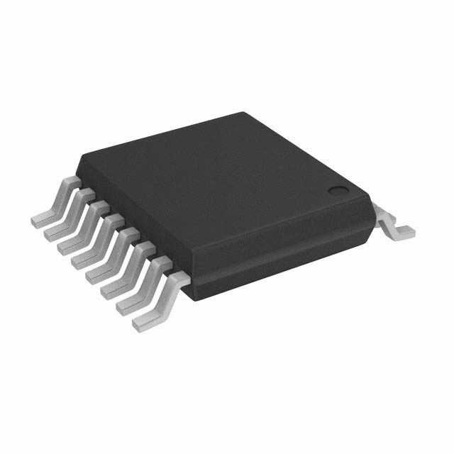
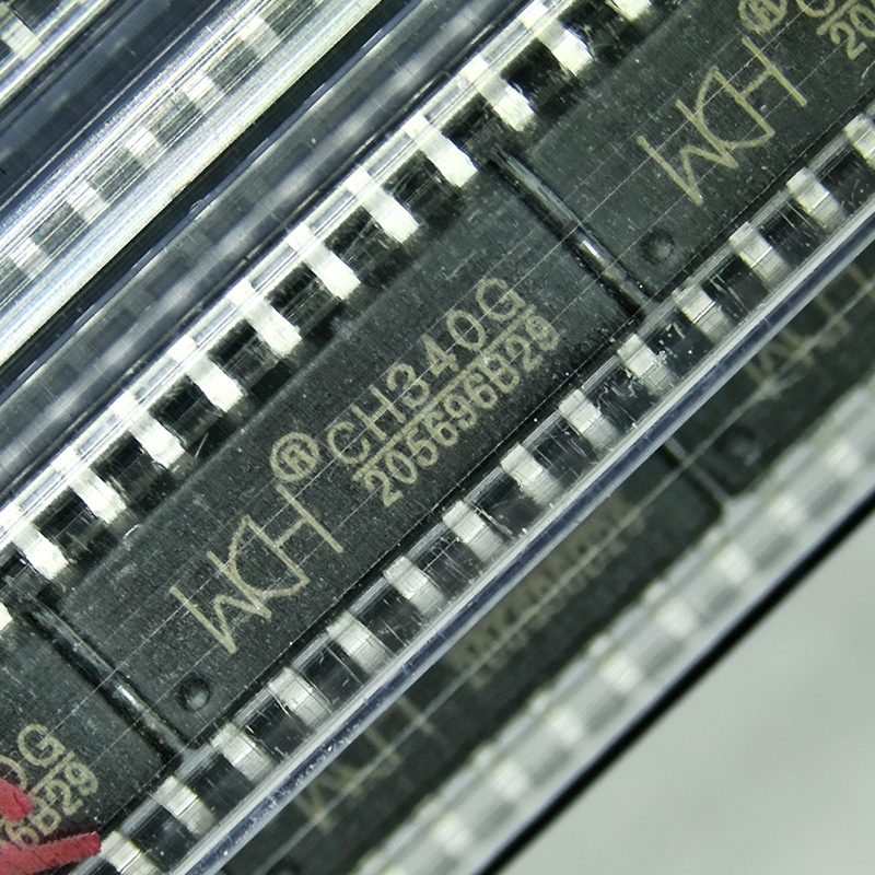
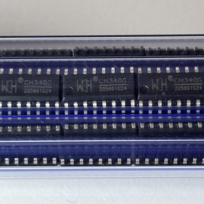
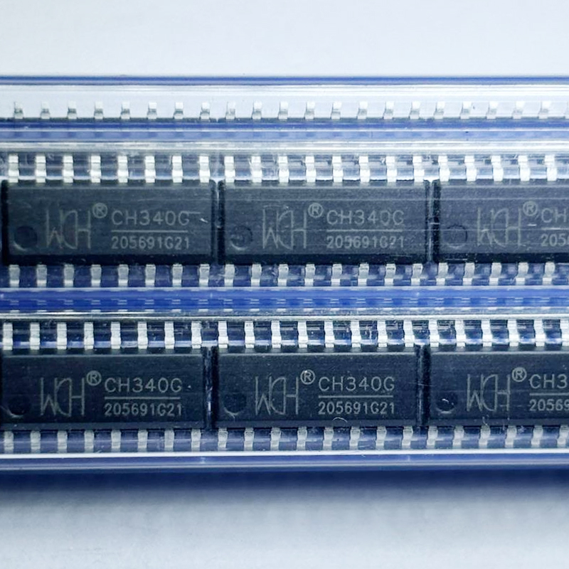
CH340G is a USB-to-UART bridge controller developed by WCH, also known as Nanjing Qinheng Microelectronics. It converts USB communication from a computer into asynchronous serial UART signals that microcontrollers, development boards, industrial controllers and other embedded devices can understand. The CH340G is widely used in USB-to-TTL adapters, Arduino-compatible boards, debugging interfaces and serial communication products. The G version uses an external 12 MHz crystal and is commonly supplied in a 16-pin SOP package.
CH340G Key Specifications
The CH340G USB-to-serial converter is designed to bridge two very different communication environments. On one side is USB, which is the standard peripheral interface found on computers. On the other side is UART, a simple asynchronous serial interface used by microcontrollers and embedded electronics.
This conversion allows a computer to communicate with a device that does not contain a native USB peripheral. Instead of redesigning the microcontroller system around USB firmware, engineers can add the CH340G and continue using a familiar TXD and RXD serial interface.
| Parameter | CH340G | Engineering Meaning |
|---|---|---|
| Manufacturer | WCH | Nanjing Qinheng Microelectronics |
| Function | USB to UART Bridge | Converts USB data to asynchronous serial communication |
| USB Interface | USB 2.0 Compatible | Connects directly to a USB host |
| Serial Interface | UART | Provides TXD and RXD communication signals |
| Clock | External 12 MHz Crystal | Provides the clock required by the CH340G version |
| Baud Rate | Common standard and high UART baud rates | Supports applications from basic debugging to faster data transfer |
| Data Format | UART-Compatible | Supports common serial data, stop-bit and parity configurations |
| Control Signals | RTS, CTS, DTR, DSR and others | Supports hardware flow control and modem-style signaling |
| Logic Environment | 3.3 V / 5 V Applications | Can be integrated into common embedded voltage systems |
| Package | SOP-16 | Easy-to-assemble surface-mount package |
| Typical Uses | USB Serial, Development Boards, Debugging | Provides an inexpensive PC-to-MCU communication bridge |
The main value of CH340G is not simply converting one connector into another. It allows existing UART-based firmware and hardware to gain a practical USB connection without adding a full USB software stack to the target microcontroller.
How the CH340G USB-to-UART Converter Works
A computer communicates with the CH340G through USB. Once the correct driver is installed and the device is recognized by the operating system, the CH340G usually appears as a virtual serial or COM port.
Software can then open that virtual serial port just as it would open a traditional RS-232-style serial interface. The major difference is that the physical connection between the computer and CH340G is USB.
Inside the IC, USB packets are translated into asynchronous UART data. Data transmitted by the computer appears on the CH340G TXD pin. Data sent from a connected microcontroller into the CH340G RXD pin is converted back into USB data and delivered to the computer.
Communicates with Windows, Linux or another USB host through the USB D+ and D− differential lines.
Translates between USB transactions and asynchronous serial UART data.
Provides TXD, RXD and additional control signals for communication with embedded hardware.
This architecture is why CH340G is frequently found on development boards. A microcontroller can continue using its simple UART peripheral, while the computer sees a convenient USB serial interface.
CH340G Pinout and Signal Functions
Understanding the CH340G pinout is important for both new PCB design and troubleshooting existing boards.
The device includes USB signals, UART signals, modem-control lines, power pins and crystal connections. Not every application needs every control signal. A simple USB-to-TTL adapter may use mainly TXD, RXD, USB D+, USB D−, power, ground and crystal connections.
| Signal Group | Typical Signals | Purpose |
|---|---|---|
| Power | VCC, GND | Supplies power and provides the circuit reference |
| USB | UD+, UD− | USB differential data connection to the host |
| UART Data | TXD, RXD | Transfers serial transmit and receive data |
| Hardware Control | RTS, CTS | Can be used for UART hardware flow control |
| Modem Control | DTR, DSR, DCD, RI | Supports additional serial status and control functions |
| Clock | XI, XO | Connects to the external 12 MHz crystal network |
| Internal Supply | V3 | Related to the internal USB transceiver supply configuration |
Before designing a PCB, engineers should always compare the schematic against the current CH340G datasheet because voltage configuration and unused control signals should be handled according to the recommended application circuit.
Why CH340G Uses a 12 MHz Crystal
The external crystal is one of the most recognizable differences between the CH340G and some newer members of the CH340 family.
The CH340G requires an external 12 MHz crystal connected to its oscillator pins. The crystal provides the timing reference required for reliable USB communication and internal serial timing.
In a typical circuit, the crystal is placed very close to the CH340G. The associated load capacitors, when required by the recommended application design, should also remain close to the IC and crystal.
Why Crystal Placement Matters
Oscillator signals are relatively sensitive. Long PCB traces add capacitance and can pick up switching noise from other sections of the board.
A compact crystal loop reduces unwanted parasitic effects and makes oscillator startup more reliable. The crystal should not be routed next to noisy switching regulators, high-current traces or rapidly changing clock signals when this can be avoided.
If a CH340G board is completely invisible to a computer, checking the 12 MHz oscillator is often more useful than immediately blaming the USB driver. A missing or unstable system clock can prevent normal USB enumeration.
Using CH340G in 5 V and 3.3 V Systems
The CH340G is commonly used in both 5 V and 3.3 V embedded environments. However, designers should distinguish between the USB transceiver supply, the CH340G supply configuration and the voltage level expected by the target UART device.
Many hobby development boards operate the CH340G from 5 V USB power. The connected microcontroller may also use 5 V logic. In other products, the target processor may use 3.3 V UART logic.
Before directly connecting TXD and RXD, check the target device's input-voltage limits. A serial signal that is acceptable for one microcontroller may exceed the absolute maximum input rating of another.
For mixed-voltage systems, engineers may need a suitable level-shifting strategy depending on the exact CH340G configuration and target device.
This is especially important in professional hardware where reliability matters more than whether a prototype happens to work on the bench.
CH340G Baud Rate and UART Communication
Baud rate describes how quickly symbols are transferred through the asynchronous serial interface. The CH340G supports the standard baud rates used by most embedded UART applications as well as higher rates for faster communication.
Common practical settings include:
- 9600 baud
- 19200 baud
- 38400 baud
- 57600 baud
- 115200 baud
- 230400 baud
- 460800 baud
- Higher supported rates where the complete system allows them
The correct baud rate must be selected on both sides of the connection. If the PC terminal is configured for 115200 baud while the target microcontroller is transmitting at 9600 baud, the result will normally be unreadable characters rather than useful text.
Baud Rate Is Only Part of UART Configuration
Both sides must also agree on data length, parity and stop bits. A common setup is 8 data bits, no parity and one stop bit, often written as 8-N-1.
When debugging serial communication, verify all of these parameters before assuming there is a hardware failure.
CH340G for Arduino-Compatible Development Boards
One of the best-known applications of CH340G is on Arduino-compatible development boards. These boards often use the CH340G instead of a more expensive USB interface controller to provide programming and serial-monitor communication.
The microcontroller itself communicates through UART. The CH340G connects that UART to the computer through USB.
The USB serial link can carry bootloader data from the computer to the target microcontroller.
Firmware debugging messages can be transmitted from the MCU to a computer terminal.
DTR can be used with external circuitry to help trigger automatic reset before programming on compatible boards.
This automatic-reset function is an excellent example of why the extra control pins on a USB-UART converter can be useful even when the final application mainly requires TXD and RXD.
Common CH340G Applications
The CH340G is useful anywhere a USB host must communicate with UART-based electronics.
- USB-to-TTL serial adapters
- Arduino-compatible development boards
- Microcontroller programming tools
- Embedded debugging interfaces
- Industrial controller configuration ports
- Router and networking device console ports
- Sensor development systems
- Serial data loggers
- GPS and GNSS interface boards
- Laboratory test equipment
- Factory programming fixtures
- Educational electronics kits
Its popularity comes from simplicity. Many embedded systems already contain a UART peripheral, so adding CH340G requires much less firmware development than implementing a full custom USB device protocol inside the main microcontroller.
CH340G PCB Layout Guidelines
Although CH340G operates at modest power levels, USB is still a high-speed differential interface compared with ordinary low-frequency microcontroller signals.
A poor PCB layout may create unstable enumeration, increased noise or intermittent operation.
- Keep USB D+ and D− traces short and well matched.
- Route the USB differential pair together.
- Avoid unnecessary stubs on the USB data lines.
- Place the 12 MHz crystal close to the CH340G.
- Keep crystal traces short and symmetrical where practical.
- Place supply decoupling capacitors close to the IC.
- Provide a low-impedance ground connection.
- Keep noisy switching-regulator nodes away from USB and crystal traces.
- Use ESD protection when the USB connector is externally accessible.
- Check USB connector shield and chassis grounding strategy.
Many "driver problems" are actually hardware problems. If one computer recognizes a CH340G board intermittently, inspect the USB connector, solder joints, cable, oscillator and PCB layout before repeatedly reinstalling software.
Understanding the CH340G Driver
When connected to a computer, the CH340G normally requires operating system support so that applications can access it as a serial port. The exact installation experience depends on the operating system and driver support available on that computer.
After successful detection, users typically see a COM port on Windows or a serial device entry on Linux and other operating systems. Applications such as terminal software, IDEs, programming utilities and custom industrial software can then open that port.
When the CH340G COM Port Does Not Appear
Start with the simple checks first. Use a known-good USB data cable. Some low-cost cables provide charging power but do not contain working data conductors.
Try another USB port and inspect the board for power. If the device receives power but never enumerates, check the USB data path and oscillator circuit.
If the hardware appears correct, then confirm whether the operating system has an appropriate CH340-compatible driver.
CH340G Troubleshooting Guide
| Problem | Possible Cause | What to Check |
|---|---|---|
| No USB Device Detected | Power, cable, oscillator or USB connection problem | Check VCC, USB cable, 12 MHz crystal, D+ and D− |
| No COM Port | Driver or enumeration problem | Check operating-system device manager and driver support |
| Unreadable Serial Data | Wrong baud rate or UART format | Match baud, parity, data bits and stop bits |
| No Data Received | TX and RX wiring error | CH340G TX should normally connect to target RX and vice versa |
| Board Resets Unexpectedly | DTR reset circuit behavior | Inspect automatic-reset capacitor and target reset wiring |
| Works Only Sometimes | Poor cable, soldering, oscillator or USB layout | Inspect connector, crystal, ground and differential traces |
| Target MCU Does Not Respond | Logic-level mismatch | Verify UART voltage compatibility between both devices |
A useful troubleshooting strategy is to separate the system into two halves. First confirm that the computer can recognize the CH340G. Then test the UART side independently.
A loopback test can also be useful. In a suitable test setup, connecting the converter's serial transmit and receive paths can help confirm that data sent from a terminal is returned correctly.
CH340G vs Other CH340 USB Serial Devices
The CH340 family contains several related parts. Engineers should not assume that every device carrying the CH340 name is identical.
One of the most visible distinctions is clock generation. The CH340G is well known for requiring an external 12 MHz crystal, while some other CH340 variants integrate more of the clock circuitry or use different package options.
This can affect:
- PCB component count
- Board area
- Package footprint
- Crystal requirements
- Available control signals
- Power configuration
- Replacement compatibility
- Manufacturing cost
When replacing CH340G with another USB-UART bridge, compare more than the basic function. Pinout, driver compatibility, voltage levels, clock requirements, modem signals, USB implementation and mechanical footprint should all be verified.
CH340G vs FT232-Type USB UART Converters
CH340G is often compared with other popular USB-to-UART bridge families. Both approaches solve the same general problem: connecting a USB host to an asynchronous serial device.
The practical choice depends on project requirements rather than brand recognition alone.
| Design Question | CH340G | Engineering Consideration |
|---|---|---|
| Cost Sensitivity | Commonly selected for cost-efficient designs | Useful for high-volume and development-board applications |
| External Clock | 12 MHz crystal required | Adds crystal and supporting PCB area |
| UART Function | USB-to-UART conversion | Suitable for general serial communication |
| Control Signals | Multiple modem-style signals available | Useful for flow control and automatic reset designs |
| Software | Requires compatible OS driver support | Confirm target operating-system environment |
| Package | SOP-16 | Relatively easy for standard SMT assembly |
For a simple serial console or development-board interface, CH340G can be a very practical solution. For specialized systems, engineers should compare driver requirements, industrial support, package size and advanced features before selecting any USB-UART controller.
How to Select and Buy CH340G Safely
Because CH340G is widely used, purchasing teams should verify both the exact part number and the source of the component.
- Confirm the exact CH340G part number.
- Verify WCH as the manufacturer.
- Check the SOP-16 package requirement.
- Confirm production lot and date-code needs.
- Check package markings and physical condition.
- Request traceability for production orders where required.
- Store and handle devices according to assembly requirements.
- Verify the latest datasheet before PCB production.
For product databases, use a clean identifier such as CH340G for the MPN. Avoid placing long marketing descriptions such as "CH340G USB to UART Serial Converter SOP-16" inside an MPN field because search engines and structured-data systems work better when identifiers remain clean.
Why CH340G Remains Popular
CH340G became popular because it solves a common problem with very little system complexity.
Designers often need a temporary or permanent serial interface for firmware programming, diagnostics, configuration and manufacturing. UART is already available on most microcontrollers, but modern computers usually do not provide traditional hardware serial ports.
The CH340G bridges that gap.
It also allows the main application firmware to remain focused on the product itself. The microcontroller does not need to spend flash memory, RAM or engineering time implementing a custom USB communications stack just to create a simple serial console.
This is especially valuable in low-cost embedded products and development tools where the USB interface is primarily intended for programming or debugging rather than becoming a central feature of the finished system.
A mature component can remain valuable even when newer alternatives exist. For many boards, predictable behavior, simple UART integration and an established software ecosystem matter more than using the newest possible USB bridge.
CH340G FAQ
What is CH340G?
CH340G is a USB-to-UART converter IC from WCH. It allows a computer USB port to communicate with microcontrollers and other devices that use asynchronous serial UART communication.
Who manufactures the CH340G?
CH340G is manufactured by WCH, also known as Nanjing Qinheng Microelectronics.
What is CH340G used for?
Common applications include USB-to-TTL adapters, Arduino-compatible boards, microcontroller programming, serial debugging, industrial configuration ports and embedded development tools.
Does CH340G need a crystal?
Yes. The CH340G version is commonly designed with an external 12 MHz crystal connected to its oscillator pins.
What package does CH340G use?
CH340G is commonly supplied in a 16-pin SOP surface-mount package. Always confirm the exact package before PCB production or purchasing.
Is CH340G USB to TTL?
CH340G is a USB-to-UART bridge. It is frequently used in USB-to-TTL serial adapters, but designers must still verify the UART voltage levels required by the target circuit.
Does CH340G work with Arduino?
Yes. CH340G is widely used on Arduino-compatible development boards to provide USB programming and serial-monitor communication.
Why is my CH340G not showing a COM port?
Possible causes include missing driver support, a charge-only USB cable, poor USB connection, missing board power, oscillator problems, damaged USB data lines or a faulty device.
What baud rate does CH340G support?
CH340G supports the common UART baud rates used by embedded systems and can support higher serial rates depending on configuration. The PC software and target device must use matching settings.
Can CH340G communicate at 115200 baud?
Yes. 115200 baud is a common operating speed for CH340G-based serial interfaces and development boards.
What are TXD and RXD on CH340G?
TXD is the serial transmit output and RXD is the serial receive input. In a typical connection, CH340G TXD connects to the target device RX and CH340G RXD connects to the target TX.
What does DTR do on CH340G?
DTR is a serial control signal. On many development boards it is used with an external capacitor or reset circuit to automatically reset the target microcontroller before firmware uploading.
Can CH340G be used with 3.3 V microcontrollers?
It can be used in many 3.3 V systems, but engineers should verify the CH340G supply configuration and the target device's UART input-voltage limits before directly connecting the signals.
Why does CH340G show unreadable characters?
The most common cause is a mismatch in baud rate, data bits, parity or stop-bit configuration. Electrical noise, poor grounding or incorrect logic levels can also corrupt serial data.
Is CH340G the same as every CH340 device?
No. The CH340 family contains multiple variants with different package, clock and feature configurations. The CH340G is especially known for using an external 12 MHz crystal.
Final Engineering Perspective
The CH340G remains one of the most recognizable USB-to-UART bridge ICs because it solves a very practical embedded engineering problem.
It allows a modern USB-equipped computer to communicate with a UART-based microcontroller without requiring the target processor to implement a complete USB device interface.
For development boards, programming tools, serial adapters and industrial configuration interfaces, this can reduce firmware complexity while providing a familiar COM-port workflow to users and engineers.
Successful CH340G design depends on more than connecting TX and RX. The 12 MHz crystal should be laid out correctly, USB D+ and D− routing should be treated as a differential pair, supply decoupling should be placed close to the device, and UART voltage compatibility should be checked before connecting the converter to a target processor.
The extra modem-control signals can also add useful system functions. DTR can support automatic microcontroller reset, while RTS and CTS can provide hardware flow control in applications that need more predictable serial data handling.
For troubleshooting, engineers should divide the problem into the USB side and the UART side. First verify that the computer recognizes the CH340G. Then verify UART baud rate, signal direction, logic level and target firmware. This approach is much faster than changing multiple hardware and software variables at the same time.
When these basic design rules are followed, the WCH CH340G USB-to-serial converter provides a simple, cost-effective and well-established bridge between USB computers and UART-based embedded electronics.