SMBT70A-13-F
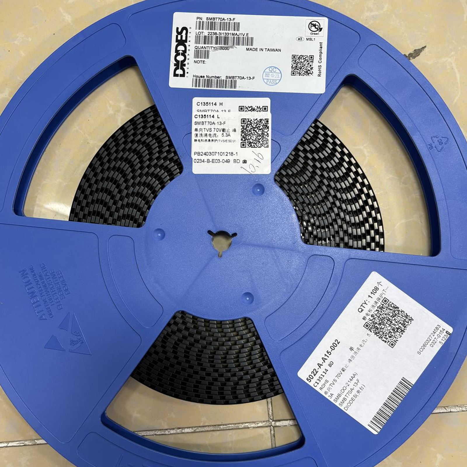
SMBT70A-13-F is a Diodes Incorporated 600W unidirectional TVS diode with 70V standoff voltage, 77.8V minimum breakdown and 100V maximum clamping voltage in an SMB tape-and-reel package for surge and transient protection.
Your reliable partner for semiconductor solutions. Flychip supports customers from R&D to mass production with electronic component supply, BOM sourcing, PCB, SMT and PCBA services.
- 20+
- Years Component Supply
- BOM
- Multi-Part Sourcing
- PCBA
- PCB / SMT Support
- Part No.:
- SMBT70A-13-F
- Manufacturer:
- Diodes Incorporated
- Category:
- TVS Diodes
- Package:
- DO-214AA, SMB
- Datasheet:
- SMBT70A-13-F.pdf
- Description:
- SMBT70A-13-F is a Diodes Incorporated 600W unidirectional TVS diode with 70V standoff voltage, 77.8V minimum breakdown and 100V maximum clamping voltage in an SMB tape-and-reel package for surge and transient protection.
- Quantity:


-
Quality Control
Supplier review, channel management and product verification before delivery.
-
Global Channels
International chip manufacturer and well-known distributor sourcing network.
-
BOM to Production
Component supply support from R&D prototype to mass production.
-
PCB / SMT / PCBA
Integrated manufacturing support to accelerate product development and delivery.
Product Details
SMBT70A-13-F Procurement & Engineering Review
This review helps engineers, buyers and sourcing teams evaluate the Diodes Incorporated SMBT70A-13-F transient voltage suppressor through surge-protection performance, clamping behavior, system-voltage compatibility, PCB placement, quality verification and production procurement.
FLYCHIP Sourcing Experience
FLYCHIP has been providing electronic components to global customers for 20 years. Our support covers R&D, prototype builds, NPI preparation, mass-production purchasing and long-term component supply planning.
- 20+
- Years of component supply experience
- 15+
- Years of channel and quality management experience
- BOM
- Multi-line sourcing and purchasing support
Quality Review Before Quotation
For SMBT70A-13-F, procurement should confirm the complete orderable part number rather than purchasing only by a generic description such as "70V TVS diode." Package size, pulse-power rating, polarity and reel configuration can materially affect production and protection performance.
Review supplier background, sourcing route, transaction history and channel stability before production quantities are approved.
Confirm manufacturer, SMBT70A-13-F order code, SMB package and tape-and-reel requirement against the approved BOM.
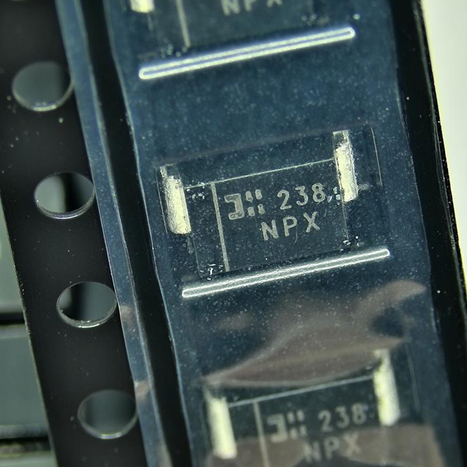
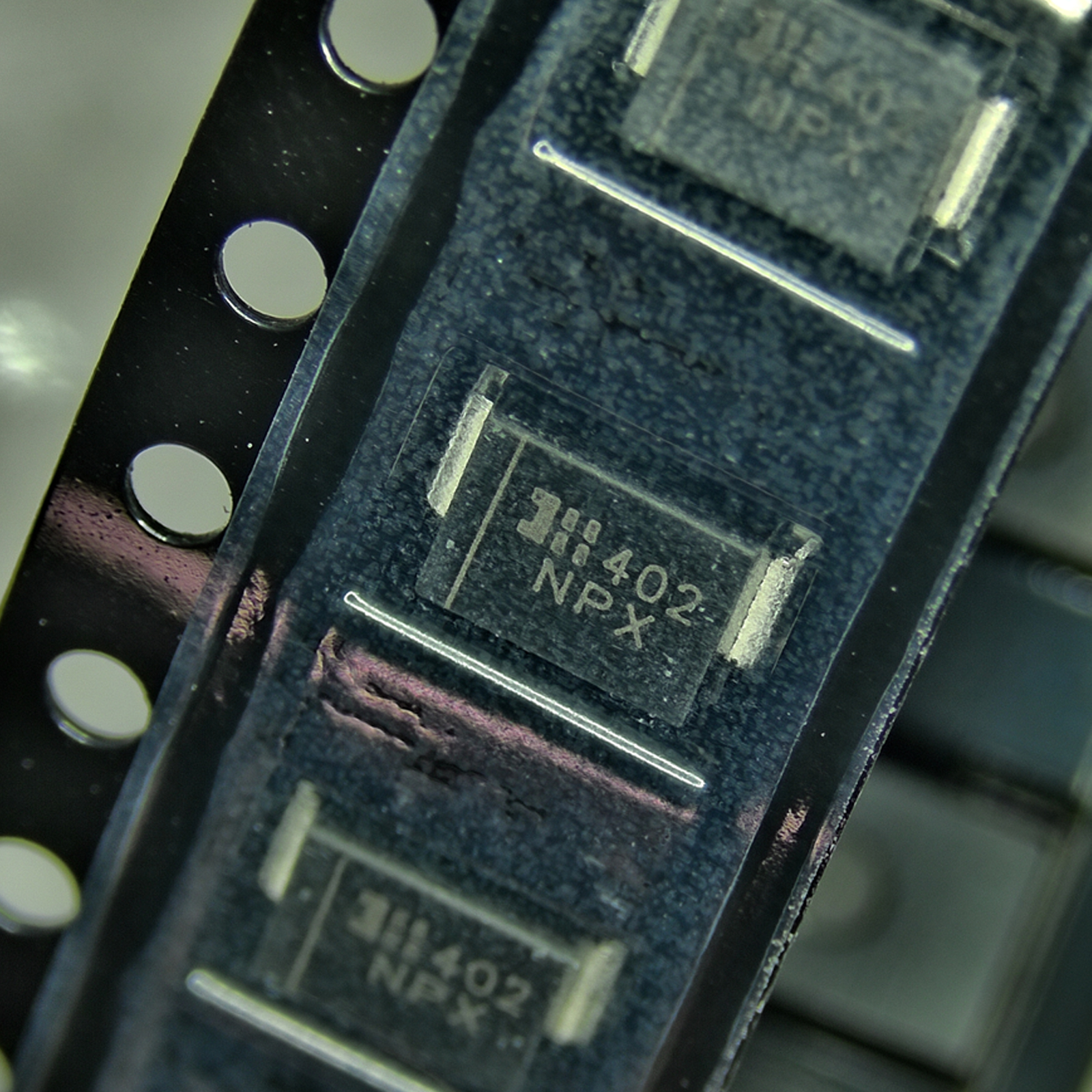
The device is unidirectional. Verify cathode-band orientation and product marking before SMT release.
Inspect body condition, terminals, cathode band, marking consistency, reel condition and available lot information before shipment.
SMBT70A-13-F Engineering Verification Notes
SMBT70A-13-F is a unidirectional transient voltage suppressor from Diodes Incorporated. It is designed to absorb short-duration surge energy and clamp excessive voltage before the transient reaches protected circuitry. The device is specifically documented as suitable for 48V backplane telecom applications.
| Parameter | SMBT70A-13-F | Engineering Meaning |
|---|---|---|
| Manufacturer | Diodes Incorporated | Use the complete manufacturer and orderable part number in BOM and procurement records. |
| Device Type | Single unidirectional TVS diode | Polarity matters. Install according to the cathode-band orientation shown in the manufacturer documentation. |
| Peak Pulse Power | 600W | This is a non-repetitive transient rating under the specified pulse waveform and temperature conditions, not continuous power. |
| Reverse Standoff Voltage | VRWM = 70V | Normal circuit voltage should remain below this level with adequate design margin. |
| Breakdown Voltage | VBR = 77.8V min / 89.5V max | Breakdown is characterized at a 1mA test current and should not be confused with maximum clamping voltage. |
| Breakdown Test Current | IT = 1.0mA | Defines the measurement condition for the specified VBR range. |
| Maximum Clamping Voltage | VC = 100V | The protected circuit must tolerate the residual clamped voltage during the specified surge event. |
| Peak Pulse Current | IPP = 5.3A | The 100V maximum clamping specification is associated with this peak pulse-current condition. |
| Reverse Leakage | IR = 5µA maximum at VRWM | Useful when checking standby leakage or high-impedance protected circuits. |
| Typical Capacitance | 290pF | Specified at 1MHz and 0V DC bias. This capacitance should be considered on high-speed or impedance-sensitive signal paths. |
| Response Time | Typically less than 1ps | The TVS junction reacts quickly, but actual system protection also depends heavily on PCB trace inductance and device placement. |
| Peak Forward Surge Current | IFSM = 100A | Specified for an 8.3ms single half-sine wave superimposed on rated load. |
| Temperature Range | -55°C to +150°C | Applies to operating junction and storage temperature range in the manufacturer data. |
| VBR Temperature Variation | 80mV/°C typical | Breakdown voltage increases with temperature; include temperature behavior in worst-case protection analysis. |
| Package | SMB | Confirm package footprint and land pattern before board production. |
| Marking Code | NPX | Manufacturer marking information can support incoming identification together with reel labels and traceability data. |
| Moisture Sensitivity | MSL 1 per J-STD-020D | Review actual packaging and factory handling requirements before SMT processing. |
| Compliance | Lead-free, RoHS compliant, Halogen and Antimony Free "Green" device | Confirm current compliance certificates where project documentation requires them. |
| AEC Qualification | No | Diodes Incorporated currently identifies the product as a standard, non-AEC-qualified device. |
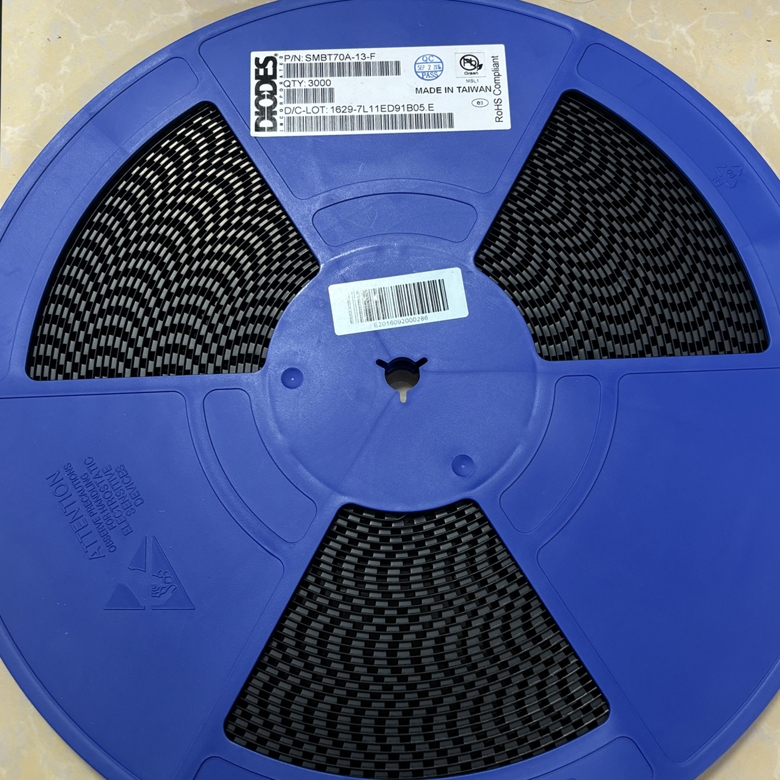
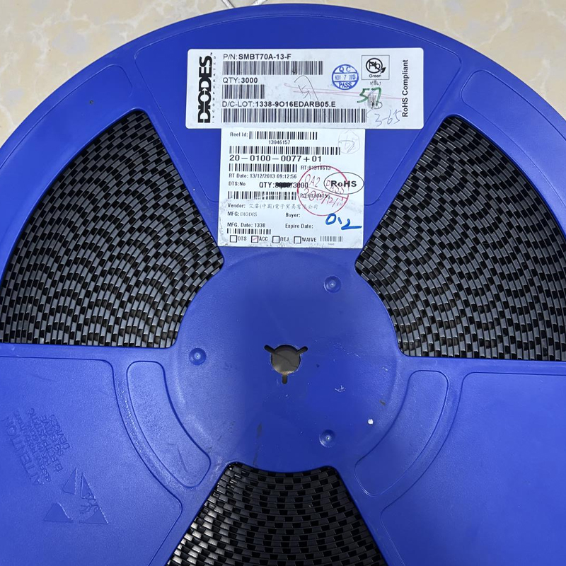
| Packing | 3,000 pcs / Tape & Reel | Confirm reel quantity and SMT feeder requirements for production purchasing. |
| Typical Application | 48V backplane telecom protection | Also applicable to suitable power-line transient suppression where voltage and surge requirements match the datasheet. |
- Start with the real maximum working voltage: the protected bus must remain below the 70V VRWM rating during normal operation, tolerance and expected steady-state variation.
- Do not select by breakdown voltage alone: the protected circuit sees clamping voltage during a surge. SMBT70A can reach 100V under its specified peak-pulse condition.
- Check the protected device limit: verify that downstream MOSFETs, regulators, ICs and capacitors can tolerate the residual transient after TVS clamping.
- Match the surge waveform: 600W is a pulse-power rating under defined conditions. Compare real pulse width, source impedance and surge energy with the manufacturer curves.
- Place the TVS close to the entry point: long PCB traces add parasitic inductance that can create extra voltage overshoot before current reaches the TVS.
- Keep the surge return path short: use a low-inductance connection from TVS to the intended return or ground node.
- Account for capacitance: 290pF typical may be acceptable on power rails but can materially load some high-speed communication lines.
- Confirm polarity: SMBT70A is unidirectional. Cathode orientation must match the protected circuit topology.
BOM Sourcing Support
TVS protection normally works together with fuses, resettable protection, input capacitors, filtering, connectors and downstream power devices. FLYCHIP can review these components as part of a broader BOM rather than treating SMBT70A-13-F as an isolated line item.
- 1
-
BOM Review
Check exact TVS order code, bus voltage, fuses, input filters, connectors, capacitors and downstream semiconductor ratings.
- 2
-
Availability Check
Review required quantity, SMB package, 3,000-piece reel requirement, lead time and sourcing feasibility.
- 3
-
Protection Review
Highlight TVS substitutions with different VRWM, VBR, VC, IPP, capacitance, polarity or package characteristics.
- 4
-
Quotation Support
Prepare sourcing options according to quantity, delivery schedule, traceability and quality documentation requirements.
SMBT70A-13-F Procurement Risk Points
TVS diodes with similar names or voltage ratings are not automatically interchangeable. The most important sourcing checks are package, polarity, standoff voltage, clamping performance, surge capability and reel configuration.
| SMBT70A-13-F | SMB package, 600W peak-pulse rating, unidirectional configuration and 3,000-piece tape-and-reel packing. |
|---|---|
| SMAT70A-13-F | Related SMA package version with a 400W peak-pulse rating and 5,000-piece tape-and-reel packing. It is not the same mechanical or power-rating option. |
| Voltage Match | A replacement should match the required VRWM and provide acceptable VBR and clamping voltage for the protected system. |
| Power Rating | Do not replace a 600W SMB device with a lower pulse-power TVS without recalculating surge requirements. |
| Polarity | SMBT70A is unidirectional. Bidirectional TVS variants may behave differently under reverse-polarity and negative transient conditions. |
| Capacitance | Replacement capacitance matters when the TVS is connected to a communication or timing-sensitive node. |
| Package Footprint | Confirm SMB package dimensions and approved land pattern instead of substituting by electrical ratings alone. |
| Compliance | Confirm RoHS, lead-free, environmental documentation and project-specific compliance requirements for the supplied material. |
Comparing alternatives only by the "70V" description can lead to incorrect protection decisions. The maximum clamping voltage of SMBT70A is 100V at the specified pulse current, so downstream component tolerance must be checked against the clamped waveform.
Supply Chain Review Method
Supply-chain review for SMBT70A-13-F combines exact product identification with packaging, marking, quality-control and project requirements. Similar TVS descriptions should not replace manufacturer-level part-number verification.
| Channel Review | Review supplier background, sourcing route, available quantity, delivery feasibility and commercial terms. |
|---|---|
| Product Identity | Confirm Diodes Incorporated, SMBT70A-13-F, SMB package and exact tape-and-reel requirement. |
| Marking Review | Product marking information includes the NPX device code together with manufacturer and date-code identification. |
| Quality Control | Review package body, terminals, polarity band, marking consistency, reel condition and documentation. |
| Engineering Coordination | Proposed TVS alternatives should be compared for VRWM, VBR, VC, IPP, pulse power, capacitance and polarity. |
| Order Management | Confirm quotation, quantity, reel requirement, shipment plan and project documentation before release. |
PCB, SMT and PCBA Solution Support
Effective TVS protection depends not only on the diode specification but also on where the device is placed and how surge current returns through the PCB. A poorly routed 600W TVS may allow substantially more voltage overshoot than expected from the datasheet clamping value alone.
Component Supply
Support SMBT70A-13-F together with fuses, filters, capacitors, connectors and other input-protection components.
Protection Layout
Place the TVS close to the transient entry point with short, wide connections to reduce parasitic inductance and voltage overshoot.
SMT Support
Verify SMB footprint, polarity, cathode-band orientation, stencil process and reel handling before assembly.
PCBA Validation
Test the protected node under representative transient conditions and inspect both TVS current path and downstream voltage response.
Recommended Purchase Decision Flow
Engineering and procurement teams should first confirm protection requirements, then verify the exact DIODES order code, package, polarity, surge rating, source and quality documentation before purchase approval.
- Confirm exact MPN: specify SMBT70A-13-F from Diodes Incorporated on the released BOM.
- Confirm normal bus voltage: verify that maximum continuous circuit voltage remains safely below 70V VRWM.
- Confirm clamp tolerance: ensure downstream circuitry can tolerate up to the specified clamping voltage during a surge.
- Confirm pulse energy: compare the real transient waveform with the 600W TVS pulse capability and manufacturer curves.
- Confirm polarity and package: require the unidirectional SMB version and correct PCB orientation.
- Confirm packing: SMBT70A-13-F is documented as 3,000 pieces per tape-and-reel.
- Control alternatives: do not approve a substitute without comparing standoff voltage, breakdown, clamping voltage, pulse current, package and capacitance.
Review Notice
This content is provided for product-detail reference, sourcing evaluation and engineering-selection support. SMBT70A-13-F electrical characteristics, pulse ratings, package information, compliance status and final application suitability should be verified against current Diodes Incorporated documentation and project-specific requirements before design or production release.
The 600W value is a transient peak-pulse rating and must not be interpreted as continuous power dissipation. Protection effectiveness depends on surge waveform, source impedance, operating temperature, PCB parasitic inductance and placement.
Official product page: Diodes Incorporated SMBT70A Product Page
Official datasheet: SMBT70A Datasheet
Manufacturer specification summary: SMBT70A is a standard, non-AEC-qualified, single unidirectional TVS with 70V reverse standoff, 77.8V minimum breakdown, 100V maximum clamp voltage, 600W peak-pulse power and SMB packaging.
Stock, pricing, available date code, lot, compliance documentation and traceability may vary by sourcing channel and should be confirmed in the current quotation.
FLYCHIP EEAT Procurement & Engineering Review · SMBT70A-13-F · Manufacturer documentation reviewed 09 October 2026.
From Component Sourcing to Production Delivery
Flychip has been providing electronic components to global customers for 20 years. We combine component supply, BOM services, PCB, SMT and PCBA support to help customers accelerate product development and delivery.
-
R&D Support
Fast sourcing support for prototype development, sample validation and early-stage engineering needs.
-
BOM Services
Multi-line BOM matching with component supply, alternative suggestions and procurement follow-up.
-
Mass Production
Stable supply coordination for production preparation, batch delivery and long-term purchasing needs.
-
Experienced Team
Over 15 years of channel management, quality control, sales management and organization management experience.
SMBT70A-13-F Technical Information
- Specifications
- FAQ
- Hot Sale
- Related Products
Specifications
- Product Attributes
- Attribute Value
- Manufacturer:
- Diodes Incorporated
- Package/Case:
- DO-214AA, SMB
- Series:
- -
- Packaging:
- Tape & Reel (TR)
- Product Status:
- Active
- Type:
- Zener
- Unidirectional Channels:
- 1
- Bidirectional Channels:
- -
- Voltage - Reverse Standoff (Typ):
- 70V
- Voltage - Breakdown (Min):
- 77.8V
- Voltage - Clamping (Max) @ Ipp:
- 100V
- Current - Peak Pulse (10/1000µs):
- 5.3A
- Power - Peak Pulse:
- 600W
- Power Line Protection:
- No
- Applications:
- General Purpose
- Capacitance @ Frequency:
- 290pF @ 1MHz
- Operating Temperature:
- -55°C ~ 150°C (TJ)
- Grade:
- -
- Qualification:
- -
- Mounting Type:
- Surface Mount
- Supplier Device Package:
- SMB
FAQ
1. How to order SMBT70A-13-F on Flychip?
You can submit an RFQ directly on this page. Our sales team will review your quantity, delivery requirements and target price, then reply with a quotation as soon as possible.
2. How does Flychip verify the quality of SMBT70A-13-F?
We work with qualified channels including international chip manufacturers and well-known distributors. Our team pays close attention to supplier review, traceability, product condition and quality control.
3. Are the price and inventory of SMBT70A-13-F updated in real time?
Inventory and prices of electronic components may fluctuate frequently. The displayed data is for reference, and the final quotation will be confirmed by our sales team.
4. What payment methods are accepted?
Wire Transfer, PayPal, Alipay, WeChat, Credit Card, Western Union, MoneyGram and Escrow may be supported depending on the order and region.
5. How is shipping arranged?
We can arrange international shipping through DHL, UPS, FedEx, TNT and other logistics channels. Tracking information will be provided after shipment.
6. What is the return or replacement process for SMBT70A-13-F?
Please contact our sales team within the specified period if there are quantity differences, wrong items, or clear external defects. The product should remain unused and in its original packaging.
7. Can I request technical support for SMBT70A-13-F?
Yes. You can contact us for datasheet, package details, pin information and sourcing assistance related to SMBT70A-13-F.
Hot Sale
Related Products
-
-
ESD9B5.0ST5G
onsemi
-
-
DESD3V3E1BL-7B
Diodes Incorporated
-
-
ESD5Z3.3T1G
onsemi
-
-
D5V0H1B2LP-7B
Diodes Incorporated
-
-
D5V0P1B2LP-7B
Diodes Incorporated
-

-
DESD5V0U1BA-7
Diodes Incorporated
-
-
ESD5Z5.0T1G
onsemi
-
-
DESD5V0U1BB-7
Diodes Incorporated
-
-
D12V0L1B2LP-7B
Diodes Incorporated
-
-
PESD2V0Y1BSFYL
Nexperia USA Inc.
-
-
DF2S5M4CT,L3F
Toshiba Semiconductor and Storage
-
-
D5V0L1B2WS-7
Diodes Incorporated
SMBT70A-13-F Sourcing & Technical Support
SMBT70A-13-F is supplied by Diodes Incorporated. This page provides key purchasing information including manufacturer, package, datasheet, stock reference, price reference and RFQ support.
As your reliable partner for semiconductor solutions, Flychip supports customers from research and development to mass production with electronic component supply, BOM sourcing, PCB, SMT and PCBA solutions.
Our sourcing partners include international chip manufacturers and well-known distributors. With rich experience in channel management, quality control and sales management, Flychip helps customers accelerate product development and delivery.
- Part Number
- SMBT70A-13-F
- Manufacturer
- Diodes Incorporated
- Package
- DO-214AA, SMB
- Category
- TVS Diodes
Quick RFQ Send your inquiry and our sales team will respond quickly.
Tips
Please check your information and try again.