

MAATSS0022TR-3000 5-Bit RF Digital Attenuator: Specifications, Control & Applications
A practical engineering guide to the MACOM MAATSS0022TR-3000, covering its 500 MHz to 2.5 GHz frequency range, 5-bit digital control, 0.5 dB attenuation steps, 15.5 dB total range, GaAs MMIC technology, MSOP-10 package, RF performance, PCB layout and wireless applications.
What Is MAATSS0022TR-3000?
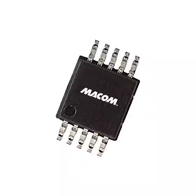
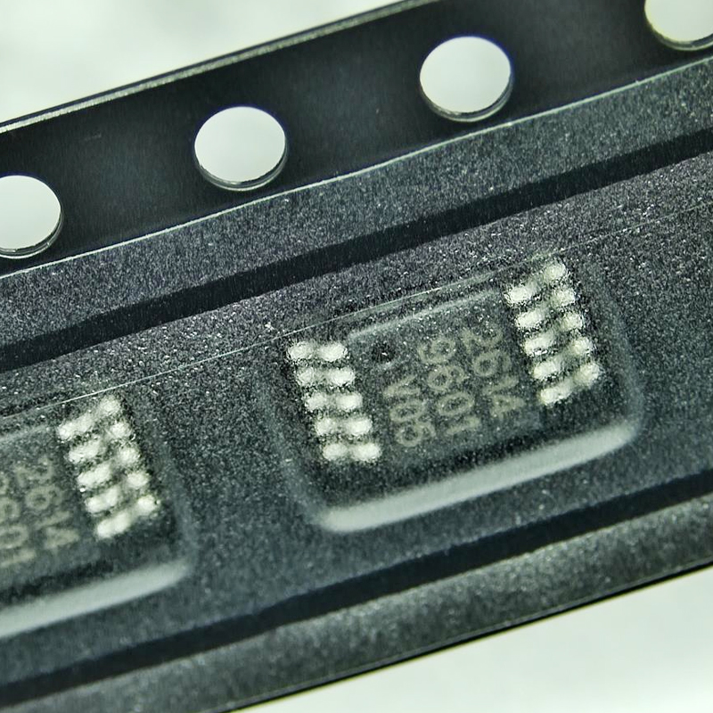
MAATSS0022TR-3000 is a MACOM 5-bit GaAs MMIC digitally controlled RF attenuator designed for signals from 500 MHz to 2.5 GHz. It provides 31 programmable attenuation states in 0.5 dB increments, from the reference state up to 15.5 dB. The device uses five individual digital control inputs, operates with a positive control supply in the +3 V to +5 V range, and is supplied in a lead-free 10-pin MSOP package. The TR-3000 ordering suffix identifies the 3000-piece tape-and-reel configuration.
MAATSS0022TR-3000 Key Specifications
The MAATSS0022TR-3000 digital attenuator is designed for RF systems where signal amplitude must be adjusted in predictable digital steps. Instead of controlling RF level with a continuously variable analog voltage, the device uses five digital control bits.
This approach is particularly useful in communication equipment because a microcontroller, FPGA or digital control circuit can select a known attenuation value repeatedly and accurately.
| Parameter | MAATSS0022TR-3000 | Engineering Meaning |
|---|---|---|
| Manufacturer | MACOM Technology Solutions | RF and microwave semiconductor manufacturer |
| Device Type | Digital RF Attenuator | Digitally reduces RF signal level |
| Technology | GaAs MMIC | Gallium-arsenide monolithic microwave integrated circuit |
| Frequency Range | 500 MHz to 2.5 GHz | Covers many sub-3 GHz wireless systems |
| Control Resolution | 5 Bits | Provides 32 digital control combinations |
| Minimum Attenuation Step | 0.5 dB | Allows relatively fine gain adjustment |
| Attenuation Range | 15.5 dB | Maximum programmed attenuation above reference state |
| RF Impedance | 50 Ω | Designed for standard RF signal environments |
| Typical VSWR | 1.6:1 | Indicates useful RF port matching across the specified band |
| Control / Supply | +3 V to +5 V | Single positive control architecture |
| Switching Time | Approximately 2 µs Typical | Allows fast digital changes between attenuation states |
| IIP3 | Up to 46 dBm Typical at +5 V | Indicates strong linearity for multi-tone RF signals |
| Input P1dB | Up to 30 dBm Typical at +5 V | Shows the approximate high-power linearity limit |
| Operating Temperature | -40°C to +85°C | Suitable for many commercial and industrial RF systems |
| Package | MSOP-10 | Compact surface-mount RF control package |
| Packaging | 3000-Piece Tape & Reel | TR-3000 ordering configuration |
The headline 15.5 dB range is only part of the story. In a real RF design, attenuation accuracy, insertion loss, impedance matching, linearity and PCB layout all matter together.
What Does TR-3000 Mean in MAATSS0022TR-3000?
The base RF device is the MAATSS0022. The additional ordering suffix identifies how the component is supplied for manufacturing.
For MAATSS0022TR-3000, the TR designation indicates tape-and-reel packaging and the 3000 suffix identifies a 3000-device reel quantity.
This distinction matters when purchasing the component for automated surface-mount production.
Base electrical device and RF attenuator function.
Tape-and-reel packaging intended for automated SMT assembly.
Identifies the 3000-piece reel ordering configuration.
The electrical function of the attenuator is determined by the MAATSS0022 device itself. The TR-3000 suffix mainly affects logistics, packaging and production handling.
How the MAATSS0022 Digital Attenuator Works
An RF attenuator reduces signal amplitude without changing the basic information carried by the RF waveform.
In MAATSS0022TR-3000, attenuation is divided into binary-weighted sections. The five control bits correspond to attenuation values of 0.5 dB, 1 dB, 2 dB, 4 dB and 8 dB.
By combining these five values, the control system can create any 0.5 dB step between the reference state and 15.5 dB.
Each control combination corresponds to a defined attenuation state, making RF gain repeatable under digital control.
A 0.5 dB least-significant bit allows small corrections without large jumps in system gain.
Five weighted attenuation sections combine to provide a total 15.5 dB programmable range.
This makes the device useful in closed-loop systems where received signal level or transmitter gain must be adjusted automatically.
Understanding the 5-Bit Attenuation Control
The five control inputs are named VC1 through VC5. Each input controls one attenuation bit.
| Control Bit | Attenuation Weight | Example Purpose |
|---|---|---|
| VC5 | 0.5 dB | Fine adjustment |
| VC4 | 1 dB | Small signal-level correction |
| VC3 | 2 dB | Medium adjustment |
| VC2 | 4 dB | Larger gain correction |
| VC1 | 8 dB | Largest attenuation bit |
The control logic is effectively active low in the published truth table. With all control bits high, the device is in its reference state. Pulling the appropriate bit low activates that attenuation section.
For example, combining the 8 dB, 2 dB and 0.5 dB sections produces approximately 10.5 dB of programmed attenuation.
Because the attenuation values follow binary weighting, firmware can convert a desired 0.5 dB step number into a five-bit control word with very little processing.
The simple parallel-control interface can be useful in systems where predictable timing matters. There is no serial command frame to decode before the RF attenuation state changes.
MAATSS0022TR-3000 RF Performance Across 500 MHz to 2.5 GHz
A digital attenuator is not ideal simply because it produces the correct nominal attenuation number. The RF signal still passes through semiconductor switches and matching structures, creating some insertion loss.
MAATSS0022 insertion loss changes with frequency. Typical values increase as frequency rises, from roughly the mid-1 dB region at the lower end of the band toward slightly above 2 dB near the upper part of the specified range.
This frequency dependence is normal for wideband RF attenuators and should be included in system gain budgeting.
Insertion Loss
Insertion loss is the signal reduction present even when the attenuator is in its reference or minimum-loss state.
For example, if a receiver chain needs a precise overall gain, the reference-state insertion loss should be included together with filter, switch, cable and amplifier losses.
VSWR
The device is designed for a 50-ohm RF environment and has a typical VSWR around 1.6:1 under the specified test conditions.
Good matching matters because reflected RF energy can affect the gain and stability of neighboring amplifiers and filters.
Attenuation Accuracy
Accuracy is not perfectly constant across frequency and attenuation state. The allowable error generally changes with both operating frequency and the selected attenuation.
This is why precision RF systems should evaluate the actual attenuation error at their intended frequency rather than relying only on the 0.5 dB nominal step size.
P1dB and IIP3: Why Linearity Matters
RF attenuators are often placed in front of sensitive receiver stages or inside transmitter gain-control paths. They must therefore handle real RF power without producing excessive distortion.
At a +5 V control supply, the MAATSS0022 datasheet lists a typical 1 dB compression input power around 30 dBm and a typical input third-order intercept point around 46 dBm under its specified test conditions.
What Is P1dB?
The 1 dB compression point describes when the device begins to deviate significantly from ideal linear behavior as RF input power increases.
It should not be treated as a preferred continuous operating power. Professional designs normally maintain suitable margin below the linearity limit.
What Is IIP3?
IIP3 is especially important in systems carrying multiple RF signals. Nonlinear behavior can combine these signals and create unwanted third-order intermodulation products.
A higher IIP3 generally indicates better large-signal linearity. This is one reason MAATSS0022 can be useful in base-station and wireless gain-control circuits.
MAATSS0022TR-3000 Pin Functions
The device uses a compact 10-pin MSOP package. Its pin arrangement separates the five digital control lines from the RF signal ports and ground connections.
| Pin | Function | Design Role |
|---|---|---|
| 1 | VC1 | Digital attenuation control input |
| 2 | VC2 | Digital attenuation control input |
| 3 | VC3 | Digital attenuation control input |
| 4 | VC4 | Digital attenuation control input |
| 5 | VC5 | Digital attenuation control input |
| 6 | RF Port 2 | RF signal connection; use required DC blocking |
| 7 | Ground | RF and circuit ground |
| 8 | Ground | RF and circuit ground |
| 9 | Ground | RF and circuit ground |
| 10 | RF Port 1 | RF signal connection; use required DC blocking |
MACOM specifies that external DC-blocking capacitors are required on the RF ports. The capacitor value should be selected so its impedance is suitably low across the intended RF frequency range.
Control Voltage and Low DC Current
MAATSS0022 uses a single positive control architecture in the approximately +3 V to +5 V range.
This is useful because many RF control systems already contain 3.3 V or 5 V digital rails.
The device also requires very little DC current compared with active RF gain blocks. Datasheet values show supply current in the microamp range under normal control conditions.
However, logic compatibility should still be checked carefully. A digital output should not be assumed to be compatible only because its nominal voltage is called 3.3 V or 5 V.
Confirm the control-high and control-low levels, sequencing and absolute maximum limits in the current datasheet before connecting an FPGA, microcontroller or level shifter.
Why MACOM Uses GaAs MMIC Technology
The MAATSS0022 is fabricated using MACOM's GaAs MMIC process. Gallium arsenide has long been used in RF and microwave semiconductors because of its useful high-frequency electrical characteristics.
For an RF attenuator, the process helps create compact switching and attenuation structures with controlled parasitic behavior.
The design also uses chip passivation to support reliability and stable performance.
GaAs technology is well suited to RF switching and attenuation over GHz-frequency ranges.
Multiple binary attenuation sections can be integrated in a small MMIC structure.
The attenuator can be digitally controlled without the DC power consumption of an active RF amplifier stage.
PCB Layout Guidelines for MAATSS0022TR-3000
At frequencies up to 2.5 GHz, physical PCB layout becomes part of the RF circuit. A schematic can be electrically correct while the final board still performs poorly because of trace geometry and grounding.
- Design RF traces for approximately 50-ohm characteristic impedance.
- Keep RF connections as short as practical.
- Place DC-blocking capacitors close to the RF ports.
- Use a continuous low-impedance ground structure.
- Connect ground pins with short paths and nearby ground vias.
- Avoid long stubs on RF traces.
- Keep fast digital control lines away from sensitive RF routing.
- Follow the recommended MACOM package footprint.
- Use controlled-impedance board construction where required.
- Evaluate connector transitions and test fixture losses.
Grounding Is More Than Connecting Pins to Ground
At RF frequencies, even a short PCB trace has inductance. A long route from a ground pin to a distant ground via may therefore behave very differently from an ideal zero-ohm connection.
For this reason, RF ground pins normally benefit from short connections and nearby vias into a solid ground plane.
At 2.5 GHz, layout should be treated as an RF structure rather than ordinary low-frequency wiring. The same attenuator can show noticeably different measured performance on two different PCB layouts.
Common MAATSS0022TR-3000 Applications
The combination of fine attenuation resolution, moderate total range, good linearity and broad 500 MHz to 2.5 GHz coverage makes the device useful in many RF gain-control systems.
- Wireless base stations
- RF gain-control circuits
- Wireless data equipment
- Wireless local loop equipment
- ISM-band radio systems
- Receiver front-end level control
- Transmitter gain adjustment
- RF laboratory equipment
- Automated RF test systems
- Signal-level calibration circuits
- Communication infrastructure
- Programmable RF signal paths
Receiver Gain Control
A receiver may experience signal levels that vary by many decibels. A digitally controlled attenuator can reduce a strong signal before it reaches a sensitive amplifier or mixer.
This can help prevent compression and preserve useful dynamic range.
Transmitter Level Adjustment
The device can also be used as part of a transmitter-level control network where fine output-power adjustment is needed.
The attenuator itself does not amplify the signal. Instead, it reduces signal level in known steps while another RF gain stage provides the necessary output power.
Automated Test Equipment
In production RF testing, programmable attenuation can be used to simulate different signal strengths without manually changing cables or fixed attenuator pads.
Practical MAATSS0022TR-3000 Control Example
Consider a wireless receiver where a microcontroller monitors the strength of the received signal.
When the RF input is weak, the controller places MAATSS0022 in its reference state to preserve maximum available signal.
As the input becomes stronger, the controller gradually increases attenuation.
If the system needs 4.5 dB of attenuation, the controller can combine the 4 dB and 0.5 dB attenuation bits.
For 7.5 dB, it can combine the 4 dB, 2 dB, 1 dB and 0.5 dB sections. For maximum attenuation, all five weighted sections combine to produce 15.5 dB.
This binary structure makes software control simple. The target attenuation can be represented as a half-decibel step number and mapped directly into the five control lines.
The resulting system can respond automatically to changes in received signal strength without any mechanical RF adjustment.
MAATSS0022TR-3000 Replacement and Equivalent Selection
A replacement should not be chosen simply because another part is also described as a 5-bit RF attenuator.
| Replacement Check | MAATSS0022TR-3000 Reference | Why It Matters |
|---|---|---|
| Frequency Range | 500 MHz to 2.5 GHz | The substitute must cover the complete application band |
| Attenuation Range | 15.5 dB | Determines maximum gain-control range |
| Step Size | 0.5 dB | Affects control resolution |
| Bit Count | 5 Bits | Changes digital control interface |
| Logic Behavior | Parallel / Active-Low Attenuation Bits | Firmware and hardware interface must remain compatible |
| RF Impedance | 50 Ω | Required for matching to the existing RF chain |
| Insertion Loss | Frequency Dependent | Changes total system gain |
| Linearity | Check P1dB and IIP3 | Important in high-power and multi-tone systems |
| Package | MSOP-10 | Footprint and pinout must match |
| Control Voltage | +3 V to +5 V | Must work with the existing digital logic rail |
A newer attenuator may offer lower insertion loss or a wider frequency range, but it may use SPI control instead of parallel control or require a different QFN footprint.
That may be attractive for a new design but inconvenient for an existing PCB.
How to Source MAATSS0022TR-3000 Correctly
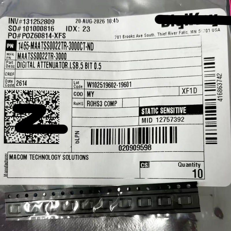
For product databases and purchasing systems, the complete manufacturer part number should remain unchanged.
Use:
Manufacturer: MACOM Technology Solutions
MPN: MAATSS0022TR-3000
Base Part: MAATSS0022
Package: MSOP-10
Packaging: Tape & Reel, 3000 Pieces
- Confirm the complete MAATSS0022TR-3000 ordering number.
- Verify MACOM as the manufacturer.
- Confirm MSOP-10 package compatibility.
- Check the 3000-piece reel requirement.
- Review lot and date-code requirements.
- Verify RoHS requirements.
- Inspect packaging and moisture handling requirements.
- Use the latest MACOM datasheet for production approval.
Do not put a full marketing description inside the MPN field. The clean manufacturer part number MAATSS0022TR-3000 is better for ERP data, search engines and structured product information.
MAATSS0022TR-3000 FAQ
What is MAATSS0022TR-3000?
MAATSS0022TR-3000 is a MACOM 5-bit digitally controlled GaAs MMIC RF attenuator covering 500 MHz to 2.5 GHz. It provides 0.5 dB attenuation steps and a total programmable range of 15.5 dB.
Who manufactures MAATSS0022TR-3000?
MAATSS0022TR-3000 is manufactured by MACOM Technology Solutions, a supplier of RF, microwave and semiconductor components.
What frequency range does MAATSS0022TR-3000 support?
The specified operating frequency range is 500 MHz to 2500 MHz, or 0.5 GHz to 2.5 GHz.
What is the attenuation range of MAATSS0022TR-3000?
The digital attenuation range is 15.5 dB above the reference state.
What is the minimum attenuation step?
The minimum programmed attenuation step is 0.5 dB.
How many control bits does MAATSS0022 use?
MAATSS0022 uses five digital control inputs corresponding to 0.5 dB, 1 dB, 2 dB, 4 dB and 8 dB attenuation sections.
What does TR-3000 mean?
TR-3000 identifies the tape-and-reel ordering configuration containing 3000 devices per reel.
What package does MAATSS0022TR-3000 use?
The device uses a lead-free 10-pin MSOP surface-mount package.
Is MAATSS0022TR-3000 a GaAs device?
Yes. MAATSS0022 is fabricated using a GaAs MMIC process designed for RF attenuation and switching performance.
What RF impedance does MAATSS0022TR-3000 use?
The device is designed for a nominal 50-ohm RF system.
Does MAATSS0022 require DC blocking capacitors?
Yes. The recommended application requires external DC-blocking capacitors on the RF ports.
What voltage does MAATSS0022TR-3000 use?
The device supports a single positive control and supply architecture in the +3 V to +5 V range. The exact logic levels should be confirmed against the current MACOM datasheet.
What is the typical switching time?
Typical rise, fall, turn-on and turn-off timing is approximately 2 microseconds under the datasheet test conditions.
What is MAATSS0022TR-3000 used for?
Typical applications include wireless base stations, wireless data equipment, wireless local loop systems, receiver gain control, transmitter level adjustment and programmable RF test equipment.
Can another 5-bit attenuator directly replace MAATSS0022TR-3000?
Not automatically. A replacement must be checked for frequency range, 0.5 dB resolution, attenuation range, insertion loss, RF power, IIP3, control logic, supply voltage, package, pinout and PCB footprint.
Final Engineering Perspective
The MAATSS0022TR-3000 is a practical example of why a digital RF attenuator should be evaluated as more than a simple "signal reduction" component.
Its five binary-weighted attenuation sections allow a digital controller to select RF attenuation in 0.5 dB increments from the reference state through 15.5 dB. This makes signal-level control repeatable and easy to automate.
The 500 MHz to 2.5 GHz frequency range covers a broad group of wireless and RF systems, while the GaAs MMIC architecture provides the linearity and switching characteristics needed for communication applications.
The parallel five-bit interface is also straightforward. Instead of sending a serial command word, the control circuit can change the attenuation state directly through five logic lines.
This simplicity can be valuable in legacy RF systems, fast control circuits and products where predictable digital timing matters.
However, the attenuator should always be considered together with the complete RF chain. Reference-state insertion loss affects gain budget, attenuation accuracy changes with frequency and selected state, and PCB transmission-line geometry influences measured RF performance.
The MSOP-10 package is compact, but operating near 2.5 GHz means ground connections, DC-blocking capacitors and 50-ohm RF traces should be laid out with RF behavior in mind rather than as ordinary digital PCB wiring.
For receiver gain control, transmitter level adjustment, wireless infrastructure and automated RF test equipment, MAATSS0022TR-3000 offers a useful balance of 0.5 dB resolution, 15.5 dB adjustment range, low-control-power operation and straightforward digital control.
For designs that need a 500 MHz to 2.5 GHz, 5-bit, parallel-controlled RF attenuator with fine 0.5 dB resolution, the MACOM MAATSS0022TR-3000 remains a component worth evaluating. Final RF, power, logic and layout decisions should always be checked against the latest MACOM datasheet and verified on production-representative hardware.