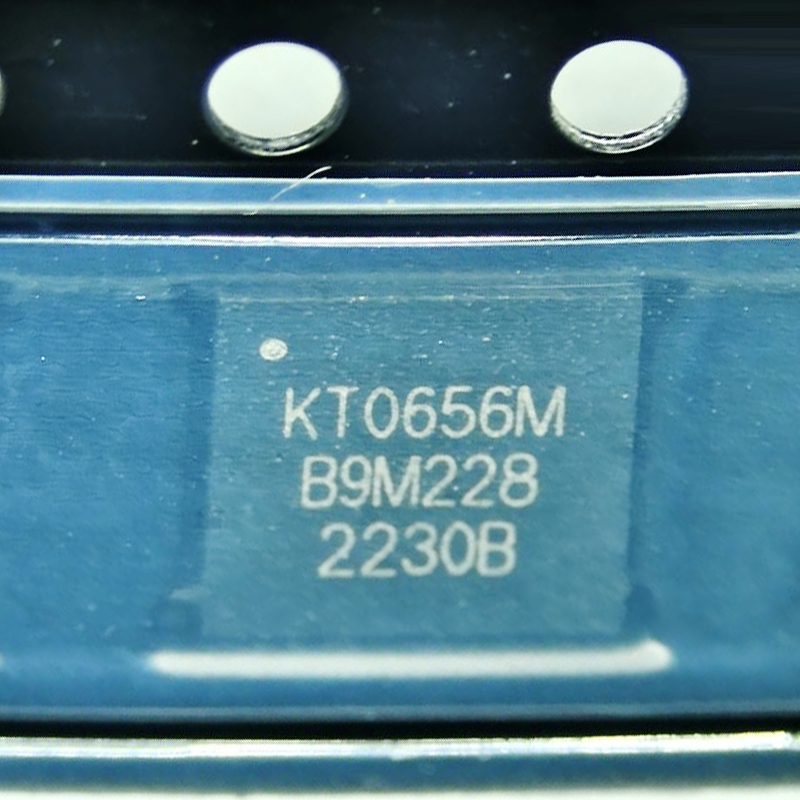
KT0656M
KT0656M is a highly integrated UHF wireless microphone receiver IC with 470–960 MHz coverage, I2C control, analog and digital audio output, low-power operation, and built-in audio processing for wireless audio designs.
Your reliable partner for semiconductor solutions. Flychip supports customers from R&D to mass production with electronic component supply, BOM sourcing, PCB, SMT and PCBA services.
- 20+
- Years Component Supply
- BOM
- Multi-Part Sourcing
- PCBA
- PCB / SMT Support
- Part No.:
- KT0656M
- Manufacturer:
- KT Micro / KTMICRO
- Category:
- RF Receivers
- Package:
- QFN-32, Exposed Pad
- Datasheet:
-
-
- Description:
- KT0656M is a highly integrated UHF wireless microphone receiver IC with 470–960 MHz coverage, I2C control, analog and digital audio output, low-power operation, and built-in audio processing for wireless audio designs.
- Quantity:


-
Quality Control
Supplier review, channel management and product verification before delivery.
-
Global Channels
International chip manufacturer and well-known distributor sourcing network.
-
BOM to Production
Component supply support from R&D prototype to mass production.
-
PCB / SMT / PCBA
Integrated manufacturing support to accelerate product development and delivery.
Product Details
KT0656M UHF Wireless Audio Receiver Engineering Review
A product-detail, engineering-selection and procurement review of KT0656M, focusing on its role as a UHF wireless microphone receiver IC, receiver-to-DSP signal path, host MCU control, digital audio integration, RF front-end design, PCB implementation, multi-channel architecture, silicon/driver validation and production sourcing.
KT0656M Product Overview
The KT0656M is a highly integrated UHF wireless audio receiver IC associated with KT Micro's wireless microphone solutions. Its role is fundamentally different from a transmitter device such as KT0646M: KT0656M belongs on the receiving side of the link.
In a typical wireless microphone receiver, the KT0656M receives the UHF RF signal, recovers the transmitted voice or audio information and passes that audio into the rest of the product. Practical receiver implementations show the device being controlled by a host processor while decoded digital audio is delivered to an audio processor through an I²S signal path.
This architecture is useful in wireless microphones, karaoke systems, smart TVs, set-top-box accessories, portable PA products and other audio systems where the RF receiver needs to connect cleanly to a modern digital audio-processing chain.
- UHF RX
- Wireless microphone receiver function
- I²C
- Host-control implementations
- I²S
- Digital audio integration
- QFN-32
- Compact receiver IC package
Maintaining this distinction is important in BOM descriptions, schematic libraries, purchasing records and technical SEO content. The two devices may operate together in a wireless microphone system but serve different sides of the RF link.
KT0656M Part Identity & BOM Definition
For engineering and procurement purposes, KT0656M should be maintained as the exact manufacturer part number rather than shortened to "KT0656", "KT06xx receiver" or a generic description such as "UHF receiver IC".
Public assembly data identifies KT0656M in a 32-pin QFN package with an approximately 5 × 5 mm body and 0.50 mm pitch. Footprint control is important because a compact exposed-pad QFN package requires accurate PCB, stencil and assembly definition.
| BOM Item | KT0656M Definition | Engineering Meaning |
|---|---|---|
| Part Number | KT0656M | Keep the complete device identifier through RFQ and production. |
| Manufacturer | KT Micro / KTMicro | Identifies the wireless-audio IC family. |
| Function | UHF wireless audio receiver | Used on the receiving side of a wireless microphone link. |
| Package | QFN-32, approx. 5 × 5 mm | Verify footprint and exposed-pad implementation before PCB release. |
| System Role | RF reception + audio recovery | Connects the wireless RF path to the downstream audio system. |
That description does not distinguish receiver and transmitter functions. Accurate functional descriptions reduce purchasing and schematic-library mistakes.
How KT0656M Fits Into a Wireless Audio Receiver
KT0656M should be viewed as the RF receiver core inside a larger audio product. The chip receives the wireless microphone signal, performs the required receiver and demodulation functions, and hands recovered audio to the downstream system.
In modern designs, the downstream device may be an audio DSP, application processor, USB audio controller or general-purpose MCU with digital-audio capability.
Antenna
RF Receiver
/ Control
/ USB Audio
Receiver IC vs Complete Receiver Product
KT0656M does not by itself define the complete user experience of a wireless microphone receiver. Antenna design, channel management, host firmware, audio DSP, analog output stages, USB interfaces and power architecture can all change the performance of the finished product.
Antenna, matching, interference environment and receiver RF implementation.
Host processor configuration, tuning and receiver-state management.
Digital or analog audio transfer into the product's processing chain.
USB audio, DSP effects, amplification and user-interface functions.
Host Control & Digital Audio Interface Strategy
Real product implementations demonstrate an architecture in which a host processor communicates with the KT0656M receiver through an I²C-style control path, while recovered voice audio is transferred through an I²S digital audio interface.
This division is useful because control traffic and continuous audio traffic have very different requirements. The MCU can configure operating parameters and monitor receiver state, while I²S moves the audio stream to a DSP or application processor.
Used in receiver implementations for configuration and host-to-receiver communication. Firmware should be validated against the actual silicon and approved driver package.
Allows decoded voice audio to move directly into a DSP, audio processor or USB-audio path without first relying on a long analog path.
Why Digital Audio Output Can Be Valuable
A digital audio path can simplify integration with modern audio processors and help avoid some of the noise problems created by routing low-level analog audio across a crowded mixed-signal PCB.
Digital output does not eliminate all audio-design risk. Clock quality, interface configuration, grounding, DSP sample-rate assumptions and power noise can still create audible problems.
Incorrect clock relationships or interface configuration can create clicks, dropouts or unreliable DSP integration even when RF reception itself is working correctly.
RF Front-End, Antenna & Receiver Sensitivity
Receiver performance cannot be judged from the KT0656M IC alone. The antenna and RF front-end strongly influence how much useful signal reaches the receiver input.
Poor matching, long RF traces, noisy digital circuitry and enclosure detuning can reduce usable reception distance even when the receiver IC itself is operating normally.
Match the actual antenna and operating band instead of copying an unrelated RF network.
Keep the receiver RF path short, controlled and isolated from noisy digital lines.
Maintain a clean RF return path and avoid unnecessary ground discontinuities.
Validate sensitivity and range after the antenna is installed in the final enclosure.
A matching network optimized for another part of the UHF range may perform poorly at the actual production frequencies.
Fast MCU, USB and clock signals can couple into sensitive receiver circuitry.
Measure the complete receiver in realistic RF environments before production release.
Audio Recovery & DSP Integration
The purpose of the receiver is not merely to show that an RF carrier exists. The final engineering goal is stable, intelligible and low-noise audio.
A useful KT0656M validation plan therefore follows the signal beyond the RF receiver and into the DSP or audio application processor.
- 1
-
RF Acquisition
Confirm stable reception at the intended channels and signal levels.
- 2
-
Demodulated Audio
Evaluate noise, dropouts and recovered voice quality.
- 3
-
I²S Transfer
Verify clocking and continuous digital audio delivery.
- 4
-
DSP Output
Validate the complete sound path, not only the receiver output.
Analog Output vs Digital Output
Community receiver implementations have demonstrated both digital I²S output and analog-audio output approaches. Which path is preferable depends on the downstream architecture.
If the product already contains a capable DSP, maintaining a digital path can simplify signal routing. If a simple analog product is being designed, analog output may reduce digital-system complexity, but noise, grounding and analog-driver requirements then become more important.
Clock, Firmware & Driver Compatibility
Receiver integration should include firmware qualification, not only hardware qualification. The host processor is responsible for initializing and controlling the receiver, so the driver package must match the actual device behavior.
Community engineering projects have reported KT0656M silicon or firmware-version differences that affected initialization code. This is a useful procurement lesson: working firmware from one sample lot should not automatically be assumed to cover every production lot.
Read and record available device or firmware identification during prototype qualification.
Keep the approved receiver driver version under project revision control.
Verify the oscillator and digital-audio clock plan with the downstream processor.
Retest initialization when material source or lot characteristics change.
A receiver IC can be electrically genuine and correctly packaged while still requiring a different driver or initialization sequence. Production sourcing should therefore retain firmware-version evidence alongside physical IQC.
QFN-32 PCB Layout & SMT Integration
Public component-library information identifies KT0656M in a compact QFN-32 package with an approximately 5 × 5 mm body and exposed center pad. The package provides excellent PCB density, but it should be treated as a precision SMT component.
| PCB / SMT Item | Recommended Review | Why It Matters |
|---|---|---|
| Footprint | Use an approved QFN-32 land pattern | Prevents pad geometry and assembly mismatch. |
| Exposed Pad | Review grounding and paste coverage | Important for electrical, thermal and assembly performance. |
| RF Input | Keep RF routing short | Helps preserve sensitivity and matching. |
| Digital Audio | Control I²S clock routing | Reduces digital noise and timing problems. |
| Stencil | Review center-pad paste aperture | Helps control voiding and package float. |
Mixed-Signal PCB Partitioning
Keep the sensitive UHF receiver section away from switch-mode converters, USB high-speed activity, display clocks and other strong digital-noise sources. A clean schematic cannot compensate for poor physical partitioning after PCB fabrication.
Dual-Channel & Multi-Receiver System Architecture
Commercial receiver products often need more than one wireless microphone channel. A common architecture uses multiple KT0656M receiver devices rather than assuming that one receiver IC automatically represents a complete dual-channel system.
Published product implementations have used two KT0656M receiver devices to recover two wireless microphone channels independently before sending audio into the host audio-processing system.
RF Link
Channel A
Channel B
/ USB
Multi-Channel Design Questions
- ✓ Confirm how multiple receiver ICs are addressed and controlled by the host MCU.
- ✓ Plan independent RF channels to minimize co-channel and adjacent-channel interference.
- ✓ Confirm how multiple I²S streams will enter the DSP or audio processor.
- ✓ Review RF isolation when multiple receiver front ends are placed on one PCB.
Engineering Selection: When KT0656M Is a Good Fit
KT0656M is most attractive when a project requires an established UHF wireless microphone receiver architecture and needs a receiver IC that can fit into a compact DSP- or MCU-controlled audio system.
Strong KT0656M Use Cases
Dedicated receiver units for handheld or portable UHF microphones.
Receivers that feed voice audio into an audio DSP or mixer.
UHF voice can be converted into digital audio for USB or application processing.
Integrated wireless microphone reception inside active speakers and amplifiers.
When Another Architecture May Be Better
- ✓ The product requires a fully digital encrypted RF protocol rather than an analog UHF architecture.
- ✓ The required regional RF band cannot be supported by the intended hardware configuration.
- ✓ Host firmware cannot support the required receiver initialization and control flow.
- ✓ The product needs another audio interface architecture that does not match the receiver design.
Receiver silicon, transmitter compatibility, antenna, firmware, clocking and DSP should all be reviewed before KT0656M enters the approved BOM.
KT0656M Prototype & Production Validation Plan
A professional KT0656M qualification process should demonstrate repeatable operation across RF, firmware and audio domains before the design enters volume production.
- 1
-
Device Bring-Up
Confirm host communication, receiver identification and initialization.
- 2
-
Frequency Test
Tune and verify all production channels intended for the target market.
- 3
-
RF Sensitivity
Compare receiver performance across multiple boards and sample lots.
- 4
-
Audio Validation
Confirm decoded audio, I²S continuity and downstream DSP behavior.
- 5
-
Interference Test
Test nearby channels, digital noise and real RF environments.
- 6
-
Pilot Build
Verify multiple assembled units before approving mass production.
KT0656M Procurement EEAT & Incoming Quality Review
Procurement control for KT0656M should extend beyond price and availability. Because the device sits at the intersection of RF, firmware and audio, a material change can affect more than basic electrical continuity.
The purchasing team should therefore preserve exact part identification and lot traceability, while engineering maintains approved driver, RF and audio validation records.
Confirm KT0656M on quotation, PO, label and incoming records.
Check package dimensions and footprint compatibility before SMT release.
Retain reel, label and supplier information for production investigation.
Verify production material with the approved initialization software.
Compare receiver operation against approved golden samples.
Confirm I²S or required audio output before approving a new supply lot.
Incoming Inspection Should Combine Physical and Functional Evidence
| IQC Item | Recommended Check | Purpose |
|---|---|---|
| Top Marking | Compare with approved samples | Flags unexpected material differences. |
| Package Geometry | Verify QFN-32 dimensions and exposed pad | Prevents incorrect packages entering SMT. |
| Firmware / ID | Read available device revision information | Helps identify driver-compatibility differences. |
| RF Sample | Receive approved transmitter signal | Confirms functional RF behavior. |
| Digital Audio | Verify valid audio stream | Confirms integration beyond basic device detection. |
A production receiver IC should be validated through part marking, package geometry, firmware compatibility, RF reception and audio output rather than appearance alone.
Alternate-Part Review
Other KT06xx or KT065x receiver devices should not automatically be treated as drop-in replacements for KT0656M. A replacement assessment should compare pinout, package, RF architecture, register map, host-control behavior, audio interface and reference circuit before BOM approval.
- ✓ Compare physical pinout and package.
- ✓ Compare register and initialization behavior.
- ✓ Compare RF input and matching requirements.
- ✓ Confirm I²S and downstream audio compatibility.
- ✓ Repeat sensitivity and interference testing.
- ✓ Repeat production receiver/transmitter pairing tests.
FLYCHIP Engineering & Procurement Position
KT0656M procurement should be linked directly to engineering qualification. RF receiver performance, firmware compatibility, digital-audio integration and assembly quality should remain part of the approved-component record, not separate from the purchasing process.
Engineering Notice
This page is intended for product evaluation, engineering selection, PCB planning, BOM control and procurement review. Exact electrical limits, RF characteristics, registers, clock requirements and operating conditions should be verified against the applicable KT0656M manufacturer documentation and project-specific measurements before production release.
From Component Sourcing to Production Delivery
Flychip has been providing electronic components to global customers for 20 years. We combine component supply, BOM services, PCB, SMT and PCBA support to help customers accelerate product development and delivery.
-
R&D Support
Fast sourcing support for prototype development, sample validation and early-stage engineering needs.
-
BOM Services
Multi-line BOM matching with component supply, alternative suggestions and procurement follow-up.
-
Mass Production
Stable supply coordination for production preparation, batch delivery and long-term purchasing needs.
-
Experienced Team
Over 15 years of channel management, quality control, sales management and organization management experience.
KT0656M Technical Information
- Specifications
- FAQ
- Hot Sale
- Related Products
Specifications
- Product Attributes
- Attribute Value
- Manufacturer:
- KT Micro / KTMICRO
- Series:
- KT06xx
- Package/Case:
- QFN-32, Exposed Pad
- Packaging:
- Tape & Reel (TR)
- Product Status:
- Active
- Frequency:
- 470MHz ~ 960MHz
- Sensitivity:
- -108dBm @ 12dB SINAD
- Data Rate (Max):
- N/A
- Modulation or Protocol:
- FM
- Applications:
- UHF Wireless Microphones, Wireless Audio Receivers
- Current - Receiving:
- < 60mA
- Data Interface:
- I2C, I2S
- Memory Size:
- N/A
- Antenna Connector:
- None - RF Input Pins
- Features:
- AFC, Auto Mute, Analog/Digital Audio Output, Audio Processing
- Voltage - Supply:
- 2.0V ~ 3.6V
- Operating Temperature:
- -30°C ~ +70°C
- Grade:
- Commercial
- Qualification:
- N/A
- Mounting Type:
- Surface Mount
- Supplier Device Package:
- QFN-32 (5mm × 5mm)
FAQ
1. How to order KT0656M on Flychip?
You can submit an RFQ directly on this page. Our sales team will review your quantity, delivery requirements and target price, then reply with a quotation as soon as possible.
2. How does Flychip verify the quality of KT0656M?
We work with qualified channels including international chip manufacturers and well-known distributors. Our team pays close attention to supplier review, traceability, product condition and quality control.
3. Are the price and inventory of KT0656M updated in real time?
Inventory and prices of electronic components may fluctuate frequently. The displayed data is for reference, and the final quotation will be confirmed by our sales team.
4. What payment methods are accepted?
Wire Transfer, PayPal, Alipay, WeChat, Credit Card, Western Union, MoneyGram and Escrow may be supported depending on the order and region.
5. How is shipping arranged?
We can arrange international shipping through DHL, UPS, FedEx, TNT and other logistics channels. Tracking information will be provided after shipment.
6. What is the return or replacement process for KT0656M?
Please contact our sales team within the specified period if there are quantity differences, wrong items, or clear external defects. The product should remain unused and in its original packaging.
7. Can I request technical support for KT0656M?
Yes. You can contact us for datasheet, package details, pin information and sourcing assistance related to KT0656M.
Hot Sale
Related Products
-
-
MICRF220AYQS-TR
Microchip Technology
-
-
SX1239IMLTRT
Semtech Corporation
-
-
SI4356-B1A-FMR
Silicon Labs
-

-
SI4362-C2A-GMR
Silicon Labs
-

-
MAX1473EUI+T
Analog Devices Inc./Maxim Integrated
-

-
CMX992Q3
CML Micro
-

-
CMX994AQ4
CML Micro
-

-
MAX2112ETI+
Analog Devices Inc./Maxim Integrated
-
-
MAX2112ETI+T
Analog Devices Inc./Maxim Integrated
-
-
TESEO-LIV3R
STMicroelectronics
-
-
M20048-1
Antenova
-
-
CMX994EQ4
CML Micro
KT0656M Sourcing & Technical Support
KT0656M is supplied by KT Micro / KTMICRO. This page provides key purchasing information including manufacturer, package, datasheet, stock reference, price reference and RFQ support.
As your reliable partner for semiconductor solutions, Flychip supports customers from research and development to mass production with electronic component supply, BOM sourcing, PCB, SMT and PCBA solutions.
Our sourcing partners include international chip manufacturers and well-known distributors. With rich experience in channel management, quality control and sales management, Flychip helps customers accelerate product development and delivery.
- Part Number
- KT0656M
- Manufacturer
- KT Micro / KTMICRO
- Package
- QFN-32, Exposed Pad
- Category
- RF Receivers
Quick RFQ Send your inquiry and our sales team will respond quickly.
Tips
Please check your information and try again.