FGA60N65SMD
FGA60N65SMD, Field Stop IGBT, 650V IGBT, 60A IGBT, onsemi, TO-3P-3L, Solar Inverter, UPS, SMPS, Welder, PFC, Power Semiconductor
Your reliable partner for semiconductor solutions. Flychip supports customers from R&D to mass production with electronic component supply, BOM sourcing, PCB, SMT and PCBA services.
- 20+
- Years Component Supply
- BOM
- Multi-Part Sourcing
- PCBA
- PCB / SMT Support
- Part No.:
- FGA60N65SMD
- Manufacturer:
- onsemi
- Category:
- Single IGBTs
- Package:
- TO-3P-3, SC-65-3
- Datasheet:
- FGA60N65SMD.pdf
- Description:
- FGA60N65SMD, Field Stop IGBT, 650V IGBT, 60A IGBT, onsemi, TO-3P-3L, Solar Inverter, UPS, SMPS, Welder, PFC, Power Semiconductor
- Quantity:


-
Quality Control
Supplier review, channel management and product verification before delivery.
-
Global Channels
International chip manufacturer and well-known distributor sourcing network.
-
BOM to Production
Component supply support from R&D prototype to mass production.
-
PCB / SMT / PCBA
Integrated manufacturing support to accelerate product development and delivery.
Product Details
FGA60N65SMDProduct, Procurement & Engineering Review
Evaluate the onsemi 650V field stop IGBT through its operating conditions, gate drive, thermal design, sourcing evidence and board-level assembly requirements.
What Is FGA60N65SMD?
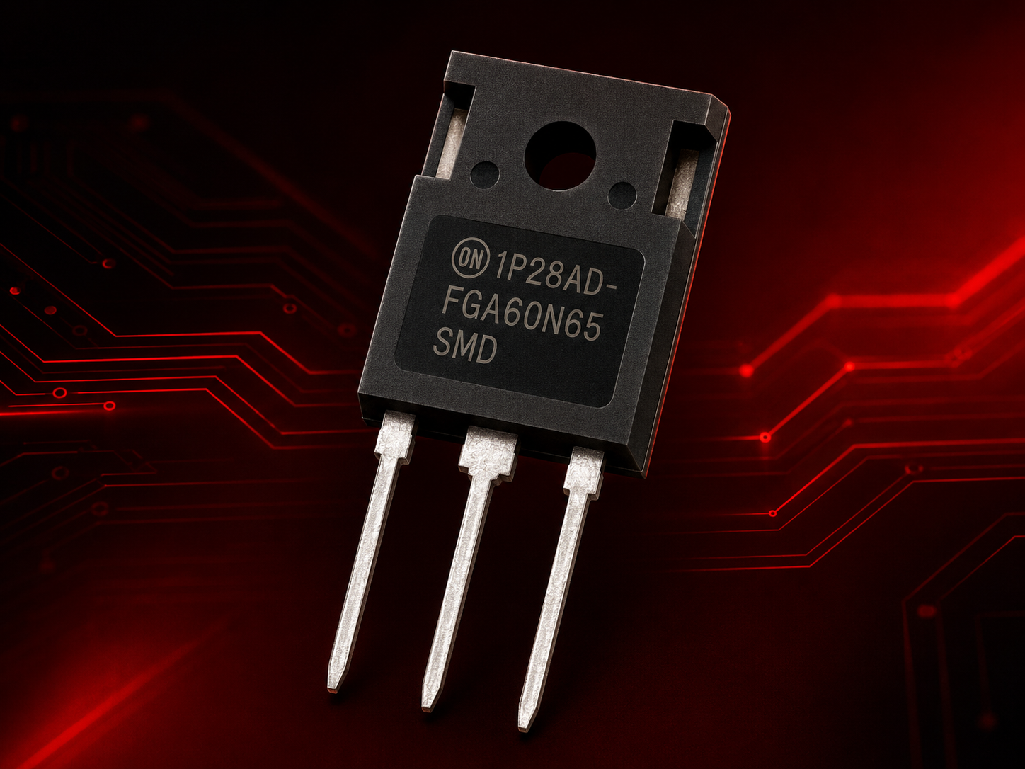
FGA60N65SMD is an onsemi 650V field stop IGBT with a co-packaged antiparallel diode in a three-lead TO-3P through-hole package. Its collector-current ratings are 60 A at a 100°C case and 120 A at a 25°C case. These temperature conditions explain why different listings show different current values. [1]
The manufacturer identifies solar inverters, UPS systems, switched-mode power supplies, welding equipment and PFC as application areas. Selecting the device for a particular circuit still requires a review of bus transients, switching current, gate drive and heat removal.
The letters "SMD" are part of the complete manufacturer part number; they do not make this device surface-mount. Keep FGA60N65SMD intact in the BOM and use the package drawing for mechanical decisions.
- 650 V
- Collector-emitter voltage limit; retain operating margin
- 60 A
- Collector-current rating at TC = 100°C
- TO-3P
- Three-lead power package for through-hole assembly
FGA60N65SMD Key Specifications
The following values are from the onsemi Revision 5 datasheet. Typical figures apply to their listed test conditions; absolute maximum ratings are limits rather than a recommended operating point. Do not combine every maximum into one operating condition. [1]
| Parameter | Published Value | Condition / Meaning |
|---|---|---|
| Manufacturer | onsemi | Full order code: FGA60N65SMD |
| Device / Diode | Field stop IGBT / co-packaged diode | Evaluate IGBT switching and diode commutation together. |
| Package | TO-3P-3L; case 340BZ | Through-hole; verify the current outline drawing. |
| VCES | 650 V | Maximum collector-emitter voltage. |
| IC | 120 A / 60 A | TC = 25°C / 100°C. |
| ICM | 180 A | Pulsed rating; pulse width limited by junction temperature. |
| VGES | ±20 V | Gate-emitter absolute maximum. |
| VCE(sat) | 1.9 V typical; 2.5 V maximum | IC = 60 A, VGE = 15 V, TC = 25°C. |
| Gate Threshold | 3.5–6.0 V; 4.5 V typical | IC = 250 µA, VCE = VGE. |
| Total Gate Charge | 189 nC typical | VCE = 400 V, IC = 60 A, VGE = 15 V. |
| RθJC | 0.25°C/W IGBT; 1.1°C/W diode | Junction-to-case thermal resistance. |
| Maximum Dissipation | 600 W / 300 W | TC = 25°C / 100°C; not converter output power. |
| Junction Temperature | −55°C to +175°C | Operating junction-temperature range. |
Engineering Selection and Gate-Drive Check
Begin with the actual switching cell. Record the highest DC-bus voltage, collector-current waveform, switching frequency, gate supply, expected case temperature and fault response. These details are more useful than selecting by the "650V 60A IGBT" description alone.
Gate threshold does not define a suitable drive voltage
The threshold test uses a very small collector current. It does not establish efficient full-load operation from a microcontroller output. The listed saturation and switching test points use 15 V gate drive. Choose a suitable driver, then verify the gate voltage at the transistor during both normal and abnormal switching.
Gate charge helps estimate average drive demand, while transition speed also depends on peak source and sink current, gate resistance and loop inductance. A resistor change can trade switching loss against overshoot and interference. Final values should follow waveform measurements on the intended board.
Include turn-off overshoot and supply excursions. The rated blocking voltage is not a suggested DC-bus operating voltage.
Keep the driver and return path close to the device. Shared inductance can change the effective gate-emitter voltage.
Coordinate current detection and controlled turn-off. Do not assume a short-circuit withstand time without an applicable manufacturer specification.
Include freewheeling intervals, dead time and reverse recovery in the loss and stress review.
Application fit must include the full operating range
A UPS may emphasize overload duration, while a welding supply may impose repeated current pulses. A solar inverter can experience a wide range of switching currents during its operating day. Validate the relevant load profile rather than treating the application label as proof of compatibility.
Switching Loss and Thermal Design
The typical energies below use VCC = 400 V, IC = 60 A, VGE = 15 V, RG = 3 Ω and an inductive load. Changing the drive, current, voltage or temperature changes the result. [1]
| Typical Energy | 25°C Case | 175°C Case |
|---|---|---|
| Eon | 1.54 mJ | 2.08 mJ |
| Eoff | 0.45 mJ | 0.78 mJ |
| Ets | 1.99 mJ | 2.86 mJ |
A calculation example, with its limits
For one turn-on and one turn-off per cycle at a fixed operating point, switching power can be estimated by multiplying total switching energy by frequency:
1.99 mJ × 20 kHz = 39.8 W
This is a calculated illustration using the 25°C typical test point. It is not a measured board result or a recommended operating frequency. For modulated current, sum the energy over the actual switching events. Keep diode and IGBT accounting consistent so that recovery-related losses are not counted twice.
Conduction heating needs a separate estimate based on current, saturation voltage and conduction time. Add the relevant losses before evaluating the cooling system; switching loss alone cannot predict junction temperature.
Example assumptions: 90°C case + 80 W × 0.25°C/W ≈ 110°C
The second example is a simplified steady-state estimate for IGBT junction-to-case heating. The complete design also includes diode dissipation, the mounting interface, heatsink, airflow and transient thermal behavior. Use transient thermal impedance for pulse conditions and retain margin below the maximum junction temperature.
FLYCHIP Sourcing Review for Power Devices
FLYCHIP component and BOM support can connect the part requirement with quotation, delivery and assembly planning. For FGA60N65SMD, the first step is to distinguish a qualified production requirement from a maintenance purchase or a new design still awaiting approval.
A production reorder should reference the approved manufacturer part number and agreed quality conditions. A maintenance purchase needs the original board requirement and failure context. A new project should add lifecycle review and candidate comparison before committing to a long-term supply plan.
Request the exact quantity, delivery schedule, manufacturer requirement, packing preference and acceptable lot/date-code range. Record any special document or inspection requirement before the quotation is finalized. This makes the offered material and the intended use easier to compare.
Quality Review Before Quotation and Shipment
For a power semiconductor, appearance and continuity checks provide limited evidence. The agreed inspection plan should state what is checked, how it is checked and what constitutes acceptance. Do not assume that a general "tested" description includes switching performance at the application voltage and current.
Review the offered source, transaction documentation and ability to resolve a discrepancy. Confirm any claimed authorization independently.
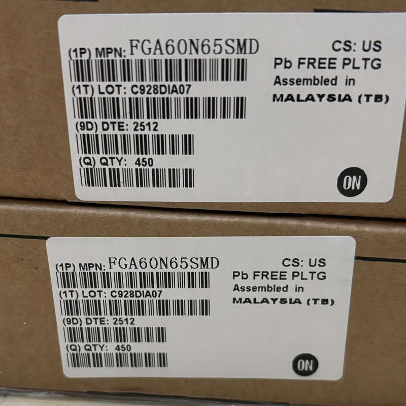
Compare labels, part identity, lot information and accompanying records. Keep the received material linked to the purchase order.
Inspect leads, body damage, signs of rework and packing protection. Verify storage or handling requirements from applicable documentation.
Agree test conditions and sample coverage when electrical inspection is required. Record results against a documented acceptance plan.
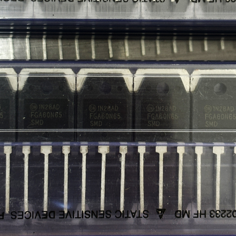
Top-marking photographs can support a record review but do not prove authenticity by themselves. If the source or condition raises a concrete concern, resolve it before release or arrange an appropriate independent examination.
BOM Support Beyond the IGBT Line Item
The surrounding components influence whether FGA60N65SMD operates as intended. A gate driver, local decoupling, current-sense circuit, gate resistors and cooling hardware belong in the same engineering review. Sourcing them as unrelated lines can hide a mismatch until assembly or test.
- 1
-
BOM Identity Check
Confirm exact part numbers, manufacturer requirements, quantities, package drawings and approved alternates.
- 2
-
Dependency Review
Check the driver, protection, thermal interface and mounting parts against the intended power stage.
- 3
-
Supply and Risk Feedback
Flag lead-time constraints, lifecycle concerns and substitutions requiring engineering approval.
- 4
-
Quotation Alignment
Align delivery dates, lot conditions, documentation and inspection scope with the build plan.
Keep a versioned BOM with the quotation and release record. If an alternate is proposed, identify exactly which technical and manufacturing checks remain open before calling it approved.
Lifecycle and Replacement Risk
The onsemi English product page displays "Active, Not Rec." This makes current manufacturer guidance an important part of a new-design decision. Confirm the latest status and applicable notices before committing to a production roadmap. [2]
A lifecycle label does not establish the quantity available from a particular supplier or the delivery date for your order. Conversely, available inventory does not establish long-term suitability for a new project. Keep technical qualification and supply planning as separate, documented decisions.
Do not approve a substitute only because it is also labeled 650 V or has a similar current rating. Different gate charge, capacitance, diode recovery and switching energy can change driver stress, heating and interference on an otherwise unchanged board.
- Compare electrical ratings at matching temperatures and test conditions.
- Check the complete package, lead arrangement and mounting requirements.
- Revisit gate resistance, dead time and protection thresholds where needed.
- Validate hot switching, thermal behavior and relevant fault cases.
- Retain engineering approval with the BOM revision and purchase record.
Supply Chain and Order Review
A quotation should identify the material being offered and the conditions under which it will be delivered. Stock counts, lead time and price are transaction-specific facts; obtain them in a dated quotation rather than treating them as permanent product specifications.
| Review Area | Required Confirmation | Useful Record |
|---|---|---|
| Source and Identity | Exact order code, manufacturer and offered source. | Quotation and available source documentation. |
| Lot Conditions | Date-code limits, mixed-lot policy and material condition. | Agreed lot requirements and label records. |
| Packing | Delivered format, split packs and handling protection. | Packing description tied to the offered quantity. |
| Quality Scope | Inspection, sampling and acceptance criteria. | Agreed plan and any required reports. |
| Delivery and Returns | Shipment date, quote validity and discrepancy process. | Written order terms and shipment records. |
The current datasheet lists 450 pieces per box. That does not establish the minimum order or delivered split-pack quantity from every supplier. Confirm the actual shipment format and distinguish manufacturer packing information from a distributor's order multiple. [1]
PCB, SMT and PCBA Coordination
FLYCHIP's component, PCB and PCBA support can help coordinate procurement with the board build. For this device, the assembly plan must explicitly include through-hole insertion and the applicable soldering and mounting process; the letters in the part number are not an assembly instruction.
Component Preparation
Match received part identity and quantities to the released BOM. Keep lots traceable through kitting and assembly.
PCB and Footprint Review
Verify the current package drawing, lead placement and power-current paths before releasing fabrication data.
SMT and Through-Hole Sequence
Coordinate surface-mount circuitry with later insertion, soldering and mechanical mounting operations as required by the build.
Thermal and Final Assembly
Define the heatsink, interface, fastening method and inspection points. Confirm electrical insulation requirements for the complete assembly.
Mechanical fit is only one part of production readiness. Excess lead stress, an inconsistent thermal interface or an unqualified fastening process can undermine a design that passed its initial electrical check. Use an assembly work instruction that reflects the actual hardware.
Recommended Purchase Decision Flow
Approve the technical requirement first, then verify that the offered material satisfies it. If engineering, sourcing or quality has an unresolved condition, carry that condition into the approval record rather than assuming another team has closed it.
Include with an RFQ: FGA60N65SMD, required manufacturer, quantity, delivery location and date, packing requirements, acceptable lot/date codes and supporting documents. Add the BOM revision and intended build stage when they affect sourcing or acceptance.
For maintenance, investigate the original failure before fitting a new device. A damaged driver, inadequate cooling or an unresolved overcurrent condition can cause the replacement to fail again even when the purchased transistor is correct.
FGA60N65SMD Product FAQ
Is FGA60N65SMD surface-mount?
Why do listings show both 60 A and 120 A?
Can a logic output drive the gate directly?
Does the 600 W rating describe output power?
Is there a co-packaged diode?
Is it suitable for a new design?
Can another 650 V IGBT replace it?
What should accompany a sourcing request?
Technical Sources and Review Basis
Reference check: September 29, 2026. Device specifications are based on manufacturer documentation. Selection and procurement guidance are engineering considerations; the numerical examples are calculations, not measured sample results.
- onsemi FGA60N65SMD datasheet, FGA60N65SMD/D, July 2026, Revision 5 - ratings, electrical characteristics, thermal data, package and ordering information.
- onsemi FGA60N65SMD product page - manufacturer product identity and the lifecycle label displayed at the time of review.
This page does not establish lot authenticity, stock availability, application approval or manufacturer authorization. Confirm current documents, offered material and project requirements before purchase or production release.
From Component Sourcing to Production Delivery
Flychip has been providing electronic components to global customers for 20 years. We combine component supply, BOM services, PCB, SMT and PCBA support to help customers accelerate product development and delivery.
-
R&D Support
Fast sourcing support for prototype development, sample validation and early-stage engineering needs.
-
BOM Services
Multi-line BOM matching with component supply, alternative suggestions and procurement follow-up.
-
Mass Production
Stable supply coordination for production preparation, batch delivery and long-term purchasing needs.
-
Experienced Team
Over 15 years of channel management, quality control, sales management and organization management experience.
FGA60N65SMD Technical Information
- Specifications
- FAQ
- Hot Sale
- Related Products
Specifications
- Product Attributes
- Attribute Value
- Manufacturer:
- onsemi
- Series:
- -
- Package/Case:
- TO-3P-3, SC-65-3
- Packaging:
- Tube
- Product Status:
- Active
- IGBT Type:
- Field Stop
- Voltage - Collector Emitter Breakdown (Max):
- 650 V
- Current - Collector (Ic) (Max):
- 120 A
- Current - Collector Pulsed (Icm):
- 180 A
- Vce(on) (Max) @ Vge, Ic:
- 2.5V @ 15V, 60A
- Power - Max:
- 600 W
- Switching Energy:
- 1.54mJ (on), 450µJ (off)
- Input Type:
- Standard
- Gate Charge:
- 189 nC
- Td (on/off) @ 25°C:
- 18ns/104ns
- Test Condition:
- 400V, 60A, 3Ohm, 15V
- Reverse Recovery Time (trr):
- 47 ns
- Operating Temperature:
- -55°C ~ 175°C (TJ)
- Grade:
- -
- Qualification:
- -
- Mounting Type:
- Through Hole
- Supplier Device Package:
- TO-3P
FAQ
1. How to order FGA60N65SMD on Flychip?
You can submit an RFQ directly on this page. Our sales team will review your quantity, delivery requirements and target price, then reply with a quotation as soon as possible.
2. How does Flychip verify the quality of FGA60N65SMD?
We work with qualified channels including international chip manufacturers and well-known distributors. Our team pays close attention to supplier review, traceability, product condition and quality control.
3. Are the price and inventory of FGA60N65SMD updated in real time?
Inventory and prices of electronic components may fluctuate frequently. The displayed data is for reference, and the final quotation will be confirmed by our sales team.
4. What payment methods are accepted?
Wire Transfer, PayPal, Alipay, WeChat, Credit Card, Western Union, MoneyGram and Escrow may be supported depending on the order and region.
5. How is shipping arranged?
We can arrange international shipping through DHL, UPS, FedEx, TNT and other logistics channels. Tracking information will be provided after shipment.
6. What is the return or replacement process for FGA60N65SMD?
Please contact our sales team within the specified period if there are quantity differences, wrong items, or clear external defects. The product should remain unused and in its original packaging.
7. Can I request technical support for FGA60N65SMD?
Yes. You can contact us for datasheet, package details, pin information and sourcing assistance related to FGA60N65SMD.
Hot Sale
Related Products
-
;;2.jpg)
-
STGD3NB60SDT4
STMicroelectronics
-

-
HGTD1N120BNS9A
onsemi
-
-
STGF7NB60SL
STMicroelectronics
-
-
FGD5T120SH
onsemi
-

-
STGB3NC120HDT4
STMicroelectronics
-
-
IKP20N60TXKSA1
Infineon Technologies
-
-
STGW30H60DFB
STMicroelectronics
-
-
STGB30M65DF2
STMicroelectronics
-
-
IKB20N60TATMA1
Infineon Technologies
-
-
STGB30V60DF
STMicroelectronics
-
-
IKW30N60DTPXKSA1
Infineon Technologies
-
-
ISL9V3040P3
onsemi
FGA60N65SMD Sourcing & Technical Support
FGA60N65SMD is supplied by onsemi. This page provides key purchasing information including manufacturer, package, datasheet, stock reference, price reference and RFQ support.
As your reliable partner for semiconductor solutions, Flychip supports customers from research and development to mass production with electronic component supply, BOM sourcing, PCB, SMT and PCBA solutions.
Our sourcing partners include international chip manufacturers and well-known distributors. With rich experience in channel management, quality control and sales management, Flychip helps customers accelerate product development and delivery.
- Part Number
- FGA60N65SMD
- Manufacturer
- onsemi
- Package
- TO-3P-3, SC-65-3
- Category
- Single IGBTs
Quick RFQ Send your inquiry and our sales team will respond quickly.
Tips
Please check your information and try again.