SCR Explained: Silicon Controlled Rectifier Working Principle, Types, Uses & Applications
Contents
What Is an SCR? How Silicon Controlled Rectifiers Control High Power with a Tiny Signal
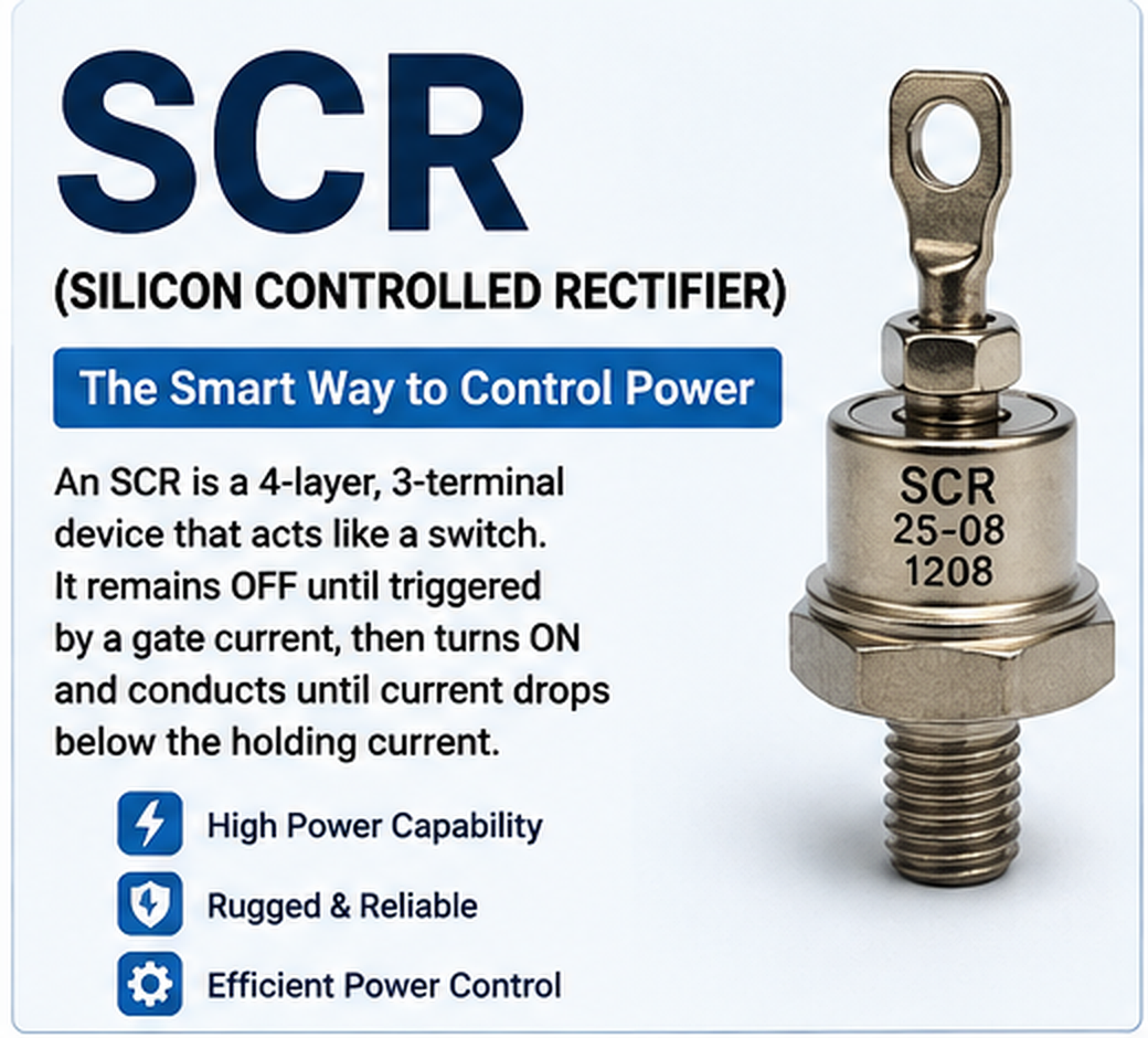
SCR is the abbreviation for Silicon Controlled Rectifier. It is one of the most widely recognized devices in the thyristor family and has been used for decades in industrial and power-electronic circuits.
The internal semiconductor structure is normally described as four alternating layers:
P-N-P-N
These four layers create three semiconductor junctions and produce the regenerative switching behavior that gives an SCR its unique latching characteristic.
What Are the Three SCR Terminals?
- Anode (A): the main current-entry terminal during normal forward conduction.
- Cathode (K): the main current-return terminal.
- Gate (G): the control terminal used to initiate conduction.
The gate normally handles only a small control signal. The much larger load current flows through the main anode-to-cathode path.
Why Is It Called a Controlled Rectifier?
The word rectifier indicates that the device normally conducts current in one primary direction. The word controlled separates an SCR from a standard rectifier diode.
A conventional silicon rectifier diode begins to conduct automatically when it becomes sufficiently forward biased. A silicon controlled rectifier, by contrast, can remain OFF even with forward voltage across it. The designer can determine when conduction starts by controlling the gate.
That difference makes an SCR useful for much more than basic rectification. It can regulate when electrical energy is delivered to a load.
Is an SCR the Same as a Thyristor?
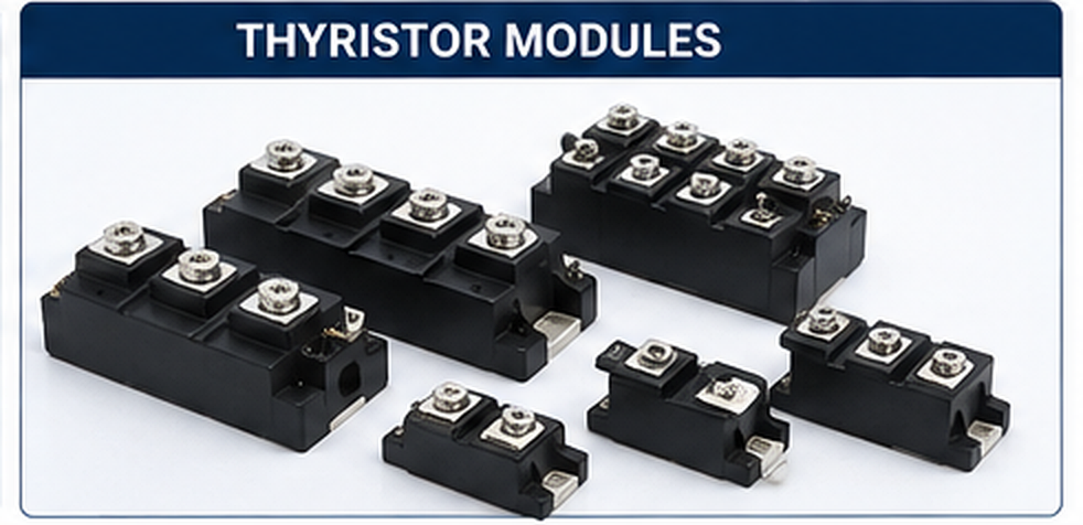
An SCR is a thyristor, but the words are not completely interchangeable. Thyristor describes a broader semiconductor family. SCR is one specific type within that family.
Other related devices include TRIACs, DIACs, silicon controlled switches and specialized thyristor structures. Industrial thyristor modules may contain SCRs, rectifier diodes or combinations of several power semiconductor elements.
Silicon Controlled Rectifier vs Silicone Controlled Rectifier
A common spelling mistake is silicone controlled rectifier. The correct electronics term is silicon controlled rectifier.
Silicon is a semiconductor material widely used in electronic devices. Silicone is a family of polymer materials commonly used in sealants, insulation, adhesives and flexible products. They are not the same material.
Similarly, the search phrase what is silicon control rectifier normally means the same thing as "what is a silicon controlled rectifier," although the second form is technically more accurate.
2. Symbol of SCR

The circuit symbol of an SCR resembles a diode symbol with an additional gate connection. This gate connection is the easiest visual clue for distinguishing an SCR from a normal rectifier diode on a schematic.
The terminals are normally labeled:
- A – Anode
- K – Cathode
- G – Gate
When the SCR is correctly forward biased and triggered, conventional current flows through the main path from the anode toward the cathode.
The gate is located close to the cathode side of the semiconductor structure. It is used to start internal regenerative action rather than continuously carry the main load current.
SCR Symbol vs Diode Symbol
| Feature | SCR | Rectifier Diode |
|---|---|---|
| Number of Main Control Terminals | Three: Anode, Cathode, Gate | Two: Anode, Cathode |
| Gate Terminal | Yes | No |
| Forward Conduction | Can be controlled by triggering | Begins automatically after sufficient forward bias |
| Latching Behavior | Yes | No SCR-style gate latching |
| Typical Purpose | Power switching and controlled rectification | Basic rectification and current steering |
3. Working Principle of SCR
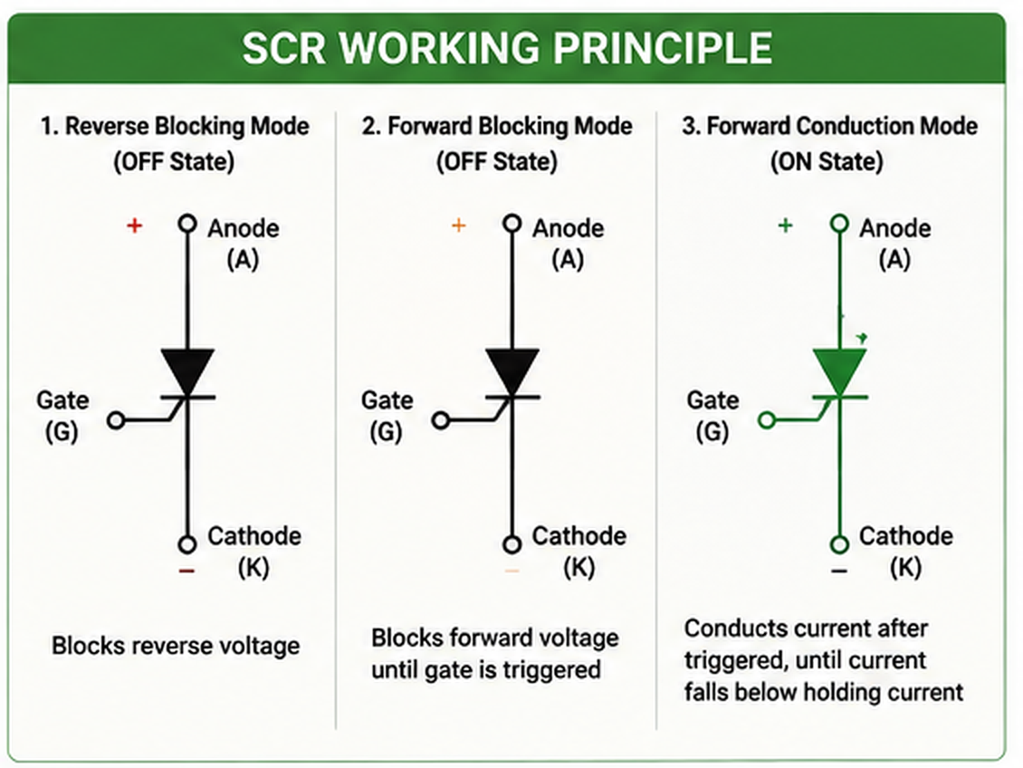
The SCR working principle can be understood by thinking of the device as an electronic latch.
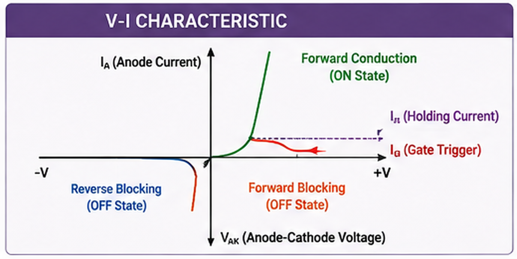
Assume that the anode is positive relative to the cathode. The SCR is now forward biased. However, unlike a normal diode, the device does not necessarily conduct immediately. It can remain in its forward-blocking state.
When a suitable positive gate current is applied between gate and cathode, carrier injection begins inside the PNPN structure. Internal regenerative feedback develops rapidly and the SCR changes from its blocking state to its conducting state.
Why Does an SCR Stay ON?
After the main current becomes large enough, the SCR becomes latched. Removing the original gate signal normally does not turn it OFF.
This behavior is one of the defining features of a silicon controlled rectifier.
To turn a conventional SCR OFF, the anode current normally needs to fall below a minimum level called the holding current. In an AC circuit, this can happen naturally when the current waveform passes through zero.
SCR Turn-On Sequence
- A positive forward voltage appears from anode to cathode.
- The SCR remains in forward blocking.
- A suitable gate current is applied.
- The internal regenerative process begins.
- The SCR switches into forward conduction.
- Main current flows from anode to cathode.
- The SCR latches when sufficient current is established.
- The original gate pulse can normally be removed.
- The SCR remains ON while current stays above its holding requirement.
- When main current becomes sufficiently low, the SCR returns to a blocking condition.
Two-Transistor Analogy
Another useful way to understand an SCR is to imagine its PNPN structure as two interconnected bipolar transistors: one PNP transistor and one NPN transistor.
The output of each transistor helps drive the other. Once a gate signal starts the process, this positive feedback rapidly increases conduction.
The analogy helps explain two important facts: a relatively small gate pulse can control a much larger main current, and removing the gate pulse after latching does not immediately turn the SCR OFF.
4. SCR Working Modes and Key Parameters
A designer should understand both the operating modes of an SCR and its datasheet parameters before selecting a device. Choosing an SCR only by its headline current rating can lead to poor reliability.
Forward Blocking Mode
In forward blocking mode, the anode is positive relative to the cathode but the SCR has not yet been triggered. Only a small leakage current flows.
From the circuit's point of view, the device behaves approximately like an open switch.
Forward Conduction Mode
After a sufficient gate signal triggers the device, the SCR enters forward conduction. Its anode-to-cathode impedance falls dramatically and substantial load current can flow.
The voltage across an operating SCR does not become zero. Its on-state voltage drop produces power loss, which becomes increasingly important as current rises.
Reverse Blocking Mode
When the anode becomes negative relative to the cathode, a conventional SCR normally blocks reverse current within its specified limits.
Designers must still respect the manufacturer's maximum reverse-voltage ratings because an SCR is not intended to withstand unlimited reverse voltage.
Important SCR Datasheet Parameters
| Parameter | Meaning | Why It Matters |
|---|---|---|
| IGT | Gate trigger current | Determines the gate current needed for reliable turn-on under specified conditions. |
| VGT | Gate trigger voltage | Helps define the voltage requirement of the trigger circuit. |
| IL | Latching current | Main current must rise sufficiently after triggering for the SCR to remain ON. |
| IH | Holding current | Defines how low main current can fall before the conducting SCR switches OFF. |
| VDRM | Repetitive peak off-state voltage | Helps determine whether the SCR can safely block the circuit voltage. |
| IT | On-state current rating | Defines current capability under specified thermal and waveform conditions. |
| dv/dt | Rate of voltage rise | Excessive dv/dt can cause unwanted triggering. |
| di/dt | Rate of current rise | Excessive current rise during turn-on can create localized heating. |
| TJ | Junction temperature | Critical for long-term device reliability. |
Gate Trigger Current – IGT
The gate trigger current is the gate current required under defined test conditions to trigger an SCR into conduction.
A reliable design should provide enough gate drive with suitable margin without exceeding the maximum gate ratings.
Gate Trigger Voltage – VGT
Gate trigger voltage describes the voltage between gate and cathode associated with triggering under specified conditions.
The driver must be designed around both gate voltage and gate current rather than assuming that only one value matters.
Latching Current – IL
Latching current is the minimum main current needed shortly after triggering so that the SCR remains conducting after the gate signal is removed.
If load current does not rise quickly enough above this level, a short gate pulse may fail to establish stable conduction.
Holding Current – IH
Holding current is the minimum anode current needed to keep an already conducting SCR in its ON state.
When current falls below the holding-current requirement, internal regenerative action stops and the SCR returns to a blocking state.
dv/dt Rating
The dv/dt rating relates to the rate at which voltage can rise across the device while it is blocking.
An excessively fast voltage change can create unwanted triggering. RC snubber networks are therefore common in circuits that contain inductive loads, switching transients or difficult line conditions.
di/dt Rating
The di/dt rating describes how rapidly main current may safely increase during SCR turn-on.
Immediately after triggering, conduction may initially occur in a limited region of the silicon die. If current rises too quickly, localized heating can damage the semiconductor before conduction spreads across a larger area.
Thermal Design
Thermal performance is just as important as electrical rating.
Engineers should evaluate junction temperature, case temperature, ambient temperature, thermal resistance, mounting method, heat-sink design, airflow, RMS current, average current, surge conditions and duty cycle.
5. Different Types of SCRs and Packaging
SCR devices range from compact components for low-current circuits to massive industrial thyristors designed for extremely demanding power systems.
Low-Power SCRs
Small SCRs are useful for triggering, alarm circuits, sensing, protection, switching and low-current control. Some use packages similar to small-signal transistor packages.
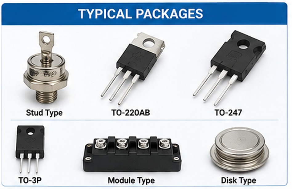
TO-220 SCR
TO-220 packaging is common in medium-power SCR applications because it provides practical PCB mounting together with a metal tab for heat removal.
Before connecting the device to a heat sink, designers must check the datasheet to determine whether the mounting tab is electrically connected to one of the SCR terminals.
TO-247 and Larger Power Packages
Higher-current silicon controlled rectifiers may use TO-247 or similar large packages that provide increased thermal capability.
They are commonly seen in industrial controllers, rectifiers, heating equipment, chargers and motor-control systems.
Stud-Mount SCR
Stud-mounted SCRs are mechanically attached to a suitable heat sink or power assembly. This construction has long been used in industrial rectifiers, motor controls and high-current power equipment.
Press-Pack and Disc Thyristors
At much higher power levels, manufacturers may use disc or press-pack thyristors. These devices are associated with high-current industrial drives, large rectifiers, power-conversion systems and other heavy-duty applications.
Thyristor Modules
Thyristor modules place one or more power semiconductor devices into a common insulated package.
Typical module arrangements can include:
- SCR + SCR
- SCR + diode
- dual SCR configurations
- half-controlled bridge arrangements
- rectifier and thyristor combinations
- application-specific power stages
Compared with assembling several individual devices, thyristor modules can simplify mechanical installation, insulation, heat-sink mounting and high-current wiring.
How to Choose an SCR Package
Package selection should be based on more than current rating. Consider available PCB space, current path, creepage distance, isolation requirements, heat-sink design, mechanical strength, airflow and serviceability.
For a compact PCB controller, a discrete package may be ideal. For an industrial cabinet handling large amounts of power, an insulated thyristor module can be easier to mount and maintain.
6. Applications of SCR
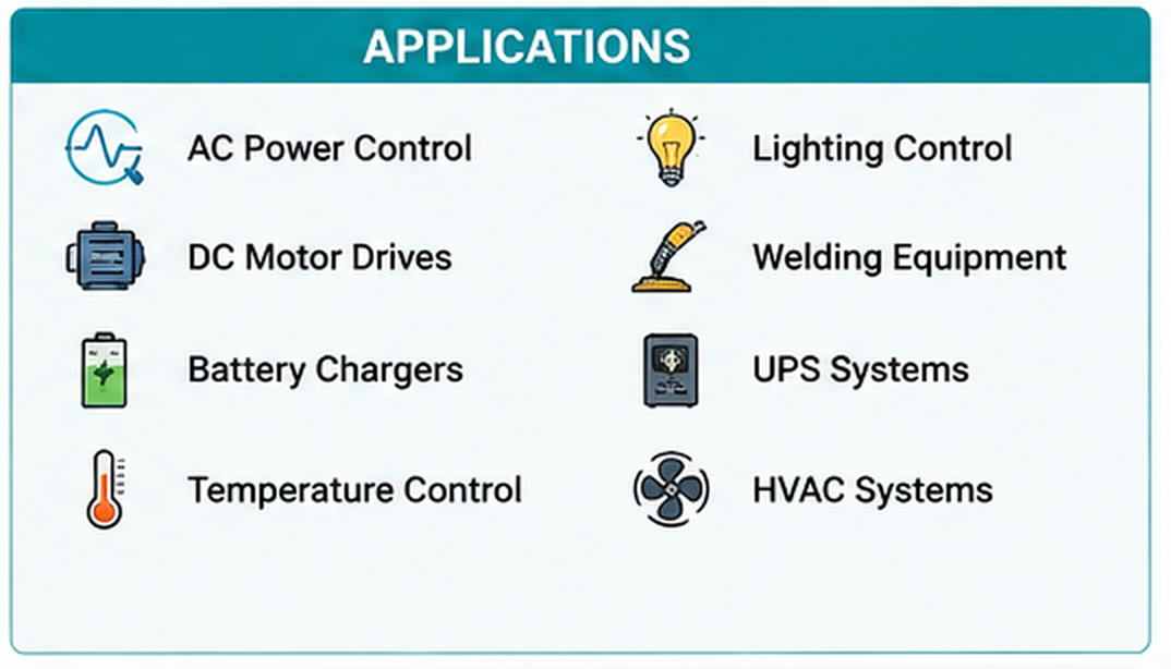
The main advantage of an SCR is the ability to control substantial electrical power using a relatively small trigger signal.
That makes the silicon controlled rectifier valuable in both simple power-control circuits and large industrial systems.
SCR Power Controller
An SCR power controller uses one or more silicon controlled rectifiers to regulate the electrical energy delivered to a load.
In AC applications, common methods include phase-angle control and zero-cross or burst firing.
Phase-angle control adjusts the point during each AC half-cycle at which conduction begins. Burst control delivers groups of complete AC cycles followed by periods with no conduction.
Industrial Heating
Industrial heating is one of the strongest application areas for SCR controllers.
Typical loads include:
- electric furnaces
- industrial ovens
- resistance heaters
- extrusion equipment
- drying systems
- heat-treatment machines
- temperature-controlled production equipment
An SCR controller can continuously adjust delivered power according to a temperature controller or automation system.
Controlled Rectifiers
A standard diode bridge provides an output mainly determined by the incoming AC waveform and circuit configuration. Replacing one or more diodes with SCR devices allows the average DC output to be adjusted by controlling the firing angle.
This approach has been widely used in industrial DC power systems and motor drives.
Motor Speed Control
SCR circuits have a long history in DC motor drives and controlled industrial power systems.
By changing when an SCR begins conducting during the AC waveform, a controller can change the average rectified voltage applied to the motor or DC bus.
Soft Starters
Powerful AC motors can draw a large amount of current when starting directly from the line.
SCR-based soft starters gradually increase the effective voltage applied to the motor during startup. This can reduce mechanical shock and limit starting current.
Battery Charging Equipment
SCR-based controlled rectifiers have also been widely used in battery chargers.
The SCR controls electrical power, while additional circuitry monitors battery voltage, current, temperature and charging requirements.
The correct charging method depends on battery chemistry, so the SCR itself should never be considered the complete battery-management system.
Crowbar Overvoltage Protection
A classic SCR application is the crowbar protection circuit.
When the monitored power-supply voltage rises above a preset limit, the protection circuit rapidly triggers an SCR across the supply.
The resulting current causes a fuse or upstream protective device to disconnect the faulty supply before prolonged overvoltage damages sensitive electronics.
Lighting and Lamp Control
SCRs and related thyristor devices have historically been used for lamp control, industrial lighting, power regulation and dimming circuits.
For direct control of both halves of an AC waveform, a TRIAC may be more convenient. High-power systems may instead use two SCRs connected in inverse parallel.
Industrial Power Conversion
Modern MOSFETs and IGBTs dominate many high-frequency converters, but SCR devices remain highly practical when very high current, high voltage, rugged operation and relatively low switching frequency are more important than fast switching speed.
7. Advantages and Disadvantages of SCR
Advantages of SCR
- High voltage capability: power SCRs are available for demanding industrial systems.
- High current capability: large devices and thyristor modules can control substantial load current.
- Low control power: a relatively small gate signal can trigger a much larger main current.
- Latching operation: continuous gate current is normally unnecessary after successful triggering.
- Good efficiency: conduction losses can be relatively low in suitable applications.
- Rugged construction: SCRs have a strong history in industrial power equipment.
- Natural AC turn-off: AC current zero crossings can simplify commutation.
- Wide package range: devices are available from small discrete packages to large industrial modules.
Disadvantages of SCR
- The gate normally cannot turn a conventional SCR OFF: main current must fall below holding current or be forced down by another circuit.
- Unidirectional conduction: one SCR does not directly control both AC polarities in the same way as one TRIAC.
- Limited high-frequency performance: SCRs are generally not preferred for modern very-high-frequency switching converters.
- dv/dt sensitivity: poor circuit design may allow fast voltage transients to create unwanted triggering.
- di/dt limits: rapid current rise can stress the device during turn-on.
- Heat sinking may be required: high-power circuits need careful thermal design.
- Gate isolation may be necessary: high-voltage systems often use transformers, optocouplers or isolated gate-drive methods.
Are SCRs Obsolete?
No. The existence of MOSFETs, IGBTs, SiC MOSFETs and other newer technologies does not automatically make SCRs obsolete.
Each semiconductor technology solves a different engineering problem.
SCRs remain attractive in line-frequency power controllers, very high-current rectifiers, industrial heating, crowbar protection, soft starters and other applications where rugged power handling matters more than very high switching frequency.
8. SCR vs SCS vs TRIAC
SCR, SCS and TRIAC devices are related to the thyristor family, but they have different terminal structures and switching behavior.
| Feature | SCR | SCS | TRIAC |
|---|---|---|---|
| Full Name | Silicon Controlled Rectifier | Silicon Controlled Switch | Triode for Alternating Current |
| Device Family | Thyristor | Thyristor | Thyristor |
| Typical Direction | Unidirectional | Generally unidirectional | Bidirectional |
| Typical Terminals | Anode, Cathode, Gate | Anode, Cathode, Anode Gate, Cathode Gate | MT1, MT2, Gate |
| Control Characteristic | Gate-triggered latching operation | Additional gate control compared with SCR | Controls both directions of AC current |
| Typical Power Use | Medium to extremely high power | Often lower-power control functions | Common in AC load control |
| Typical Applications | Rectifiers, heating, drives, soft starters, protection | Timing, switching and specialized control | Dimmers, heaters, fans and AC switching |
SCR vs SCS
SCS stands for Silicon Controlled Switch. Its PNPN structure is related to the SCR, but the SCS normally provides additional gate control.
An SCS is generally associated with switching, pulse, timing and lower-power control circuits rather than the high-power controlled rectification roles commonly associated with large SCRs.
SCR vs TRIAC
The most important difference between an SCR and a TRIAC is current direction.
A conventional SCR is primarily a unidirectional controlled device. A TRIAC can conduct current in both directions after appropriate triggering.
For this reason, one TRIAC is convenient for many single-phase AC loads such as heaters, lamps and small motor controls.
However, two SCRs connected in inverse parallel can also control both halves of an AC waveform and may be preferred in demanding industrial power systems.
SCR vs Silicon Rectifier Diode
A silicon rectifier diode has two terminals and responds mainly to the voltage polarity across it.
An SCR adds a gate terminal that allows the circuit to decide when forward conduction should begin.
That single control feature transforms the device from a basic rectifier into a controllable power switch.
SCR vs MOSFET and IGBT
SCRs, MOSFETs and IGBTs can all act as power-control devices, but they are optimized for different operating conditions.
| Feature | SCR | MOSFET | IGBT |
|---|---|---|---|
| Turn-On Control | Gate trigger | Gate voltage | Gate voltage |
| Normal Gate Turn-Off | No for conventional SCR | Yes | Yes |
| Switching Frequency | Usually lower | Very high capability | Medium to high depending on device |
| High-Power Capability | Excellent | Application dependent | Excellent |
| Typical Strength | Rugged line-frequency and high-power control | Fast switching | High-power controllable switching |
9. Conclusion
An SCR, or Silicon Controlled Rectifier, is a three-terminal PNPN thyristor designed for controlled power switching.
Its key feature is latching behavior. The SCR can remain in forward blocking even when voltage is applied, switch into conduction after an appropriate gate trigger and continue conducting after the gate pulse disappears as long as sufficient anode current remains.
This behavior explains why SCR devices are effective in SCR power controller systems, controlled rectifiers, industrial heaters, DC motor drives, soft starters, battery chargers, crowbar protection circuits and heavy industrial power equipment.
For component selection, current and voltage ratings are only the starting point. Engineers should also check gate trigger current, gate trigger voltage, latching current, holding current, repetitive off-state voltage, surge capability, dv/dt, di/dt, thermal resistance, junction temperature, cooling requirements and package construction.
The comparison with other semiconductor devices is equally important. A TRIAC offers bidirectional AC conduction. A silicon rectifier diode provides uncontrolled rectification. MOSFETs provide very fast controllable switching. IGBTs are useful in many modern high-power converters. The SCR remains especially valuable when rugged, efficient and reliable controlled switching is needed at high voltage or current.
The abbreviation SCR does not always mean Silicon Controlled Rectifier. Context determines the correct definition.
In diesel and automotive searches, terms such as diesel SCR system, Cummins SCR system, SCR system Cummins or SCR system fault usually refer to Selective Catalytic Reduction, an exhaust-emissions system rather than an electronic thyristor.
Searches for single central record or what is single central record normally refer to record-keeping or safeguarding systems. Searches such as FightLite SCR, flight lite SCR, Utah SCR, PRT SCR Windows, images SCR or what is a SCR in reading can represent completely different products, organizations, software terms or educational concepts.
For power electronics, semiconductor components, rectifiers, thyristors and electrical control systems, SCR normally means Silicon Controlled Rectifier.
Frequently Asked Questions About SCR
What is SCR?
In electronics, SCR stands for Silicon Controlled Rectifier. It is a three-terminal PNPN thyristor that uses a gate signal to start conduction between its anode and cathode.
What does an SCR do?
An SCR switches or controls electrical power. A small gate signal can trigger conduction of a much larger load current.
What are the three terminals of an SCR?
The three SCR terminals are the anode (A), cathode (K) and gate (G).
Is an SCR a thyristor?
Yes. A silicon controlled rectifier is one of the most common types of thyristor. Thyristor is the broader device family.
How does an SCR turn ON?
A forward-biased SCR normally turns ON when a suitable gate current triggers its internal regenerative switching process.
How does an SCR turn OFF?
A conventional SCR normally turns OFF when its main current falls below the holding-current requirement. In AC circuits, this can occur naturally around a current zero crossing.
What is the difference between latching current and holding current?
Latching current is the main current required shortly after triggering so that the SCR remains ON when the gate signal is removed. Holding current is the minimum current needed to keep an SCR conducting after it is already fully ON.
What is an SCR controller?
An SCR controller is a circuit or system that uses silicon controlled rectifiers to control power delivered to a load. Common examples include heater controllers, industrial power regulators, motor drives and controlled rectifiers.
What is an SCR power controller?
An SCR power controller regulates AC or DC power using SCR devices. Industrial AC controllers commonly use phase-angle firing or zero-cross/burst control.
What is the difference between SCR and TRIAC?
An SCR normally conducts in one direction, while a TRIAC can conduct in both directions. This makes TRIACs convenient for many AC loads, while SCRs remain popular in high-power controlled rectification and industrial power systems.
What are thyristor modules?
Thyristor modules are packaged assemblies containing SCRs, diodes or related power semiconductor combinations. They simplify mounting, insulation and thermal management in industrial systems.
Is a silicon rectifier diode the same as an SCR?
No. A rectifier diode has two terminals and conducts automatically under suitable forward bias. An SCR has a third gate terminal that allows the start of forward conduction to be controlled.
What does SCR system fault mean?
The meaning depends on context. In a diesel vehicle, an SCR system fault usually refers to the Selective Catalytic Reduction emissions system. In power electronics, SCR normally refers to a Silicon Controlled Rectifier.
Why are SCRs still used today?
SCRs remain useful because they can handle high voltage and current efficiently, provide rugged industrial operation and work especially well in line-frequency power control, heating, rectification, motor starting and protection applications.